Previous posts in this category include: ” A turn-of-the-century French sextant”, “A Half-size Sextant by Lefebvre-Poulin”, ” A Fine Sextant by Spencer, Browning and Co”, “A C19 Sextant Restoration” , “Making a Keystone Sextant Case” , “Restoring a C. Plath Drei Kreis Sextant” , “Heath Curve-bar sextant compared with Plath” , “A Drowned Husun Three Circle Sextant”, ”Troughton and Simms Surveying Sextant” , “A Sextant 210 Years On” , “A fine sextant by Filotecnica Salmoiraghi”, “A British Admiralty Vernier Sextant”, “An Hungarian Sextant via Bulgaria” , “A Half-size Sextant by Hughes and Son” and “A Fine C Plath Vernier Sextant”, “Heath and Co’s Best Vernier Sextant.” and “An Early C19 Ebony Quadrant Restored”.
A month or two ago, I acquired an ancient ebony-framed quadrant in a sorry state, with several important parts missing. Figure 1 shows the front view of the instrument as received and Figure 2 shows the back.
Figure 1 : Front, as found.
Figure 2 : Rear as found.
The pictures show clearly what was missing and damaged so I will not list them here, but instead digress to try to estimate the date of the instrument. Many ebony-framed octants were made and were often called “Hadley’s quadrant” or simply “a Hadley”. Most of them bear no maker’s name, though some of them, if divided by Ramsden, will bear evidence of this on the main scale. Hand-divided quadrants were of a large radius, 15 inches (380 mm) or more. The improvements due to Ramsden-type dividing engines allowed the radius to be reduced with no loss of accuracy, and most nineteenth century wooden instruments had a radius of about 9 inches (230 mm). The size of my new example lies somewhere between, at about 11½ inches (290 mm). Early illustrations of quadrants in use often show it being held by the frame, as no handle was provided, and the absence of a handle or any trace of one ever having been present, leads me to believe that this quadrant is relatively early, but after the advent of machine dividing in around 1767 (the description of Ramsden’s second engine was published in 1777 but his first engine dates to perhaps ten years before this).
Two further archaic features are the presence of a back sight pinhole or pinule and the design of the mirror brackets. I will borrow the words of W E May in his “A History of Marine Navigation” (1973, ISBN 0 85429 143 1) to explain the back sight: By altering the angle of the horizon glass and moving the eyepiece to a position close to it on the same radius, the octant could be used for what was called a ‘back observation’, when the horizon opposite to the object instead of below it was used. The angle measure was then the complement of the altitude….It is extremely doubtful whether the back observation was ever used in practice.” The light rays reaching the secondary mirror and pinule from the index mirror pass through the clear part of the normal horizon glass before being reflected into the eye by the secondary mirror, while the horizon is viewed through a slot in the silvering of the latter (Figure 3).
Figure 3 : Mirror and pinule for back sight.
Although the index mirror bracket was absent, the other two mirror brackets allowed me to study the design. Two screws pass through threaded holes in the back of the bracket and bear upon the back of the upright of an angle bracket. The vertical edges of the bracket are folded over so that when the screws are tightened, they draw the mirror back against vertical ridges on the front of the upright. Figure 4 shows the edges of the new index mirror bracket being folded over a steel pattern.
Figure 4: Edges of new index mirror bracket being formed.
If the ridges on the upright do not lie in the same plane, the mirror glass will be distorted and Peter Dollond pointed this out to Nevil Maskelyne, the Astronomer Royal, in a letter of February, 1772. Among other matters, he described the now modern practice of sitting the mirror against three points and with springs or lugs on the front of the bracket bearing on the mirror opposite these points. Figure 5 shows this practice had been adopted in a sextant made in about 1790.
Figure 5 : Peter Dollond’s method of securing mirror.
Thus, I tentatively date the quadrant as being after 1767, but not much later, as Dollond’s method of securing mirrors seems to have been rapidly adopted.
To return to the construction of the new index mirror bracket, after folding the sides and forming the retaining folds on the edges of their front I soldered the top to the sides. Figure 6 shows this being done, with a weight used to hold everything in place while the solder froze.
Figure 6 : Soldering top of index bracket to back and sides.
The holes for the fixing screws can be seen and after filing the top to its final shape, I riveted two threaded bushes in place. Figure 7 shows an exploded view of the completed bracket with its angle plate, while Figure 8 shows the completed bracket and mirror in place.
Figure 7 : Index mirror and bracket, exploded view
Figure 8 : Completed Index mirror bracket.
The next part to receive my attention was the pinules or pin hole sights. Actually, the holes are about 2 mm in diameter, rather larger than your usual pin…
All that remained to guide me was the base of one of them, so I laboriously cut out two discs of 3 mm brass sheet, filed them to shape and married one of them to the existing base by cutting a slot in it, applying solder and smoothing to shape with a file (Figure 9). I copied the base for the other sight. The standard sight has two holes in in, one in line with the silvered edge of the horizon glass and the other a few mm higher, so as to admit more light from the horizon to the eye when there is poor contrast between the sea and the sky. Even small increases in light intensity give worthwhile increases in contrast. I also fashioned a little cover (visible in Fig 11) that can be swung into place to cover one or other of the holes. The back sight has only one hole, aligned with the slot in the silvering of its mirror.
Figure 9 : Pin hole sight repair.
If you compare Figure 3 with Figure 10, you will see that in the latter , there is a defect in the wood of the frame. I made this good with car body filler, stained black with grouting stain, and then sanded to shape and smoothness, followed by a few coats of French polish until it matched the finish of the surrounding wood.
Figure 9 : Damaged frame (see also Fig 3)
The missing horizon shade glass was replaced by a disc of ruby red glass, which I cut out with a trephine. If you look carefully at Figure 1, you will see a rectangular slot just below the base of the horizon shade on the photograph. This is also visible on the back, and there is a further slot higher up which is occupied by the base of the horizon shades, so that the latter can be, as it were, unplugged and transferred to the lower slot, to provide shades when using the back sight.
Apart from a general clean-up and fitting a piece of Ivorine for the name plate, that completed repairs to the front. The most important item missing from the back was the washer and screw that secures the index arm bearing journal to the frame. Unfortunately, the screw had broken off and I had to drill it out and re-tap for a slightly larger size, but the washer presented no problems. The square hole in the washer has to fit closely over the square on the end of the bearing, as any tendency for it to turn might tend to loosen or tighten the screw and affect the adjustment of the tapered bearing.
It was a relatively simple matter to copy one of the legs and to make sundry new washers and screws. Two thumb screws lock the adjustments to the index and back sight mirrors and it was not too difficult to copy the remaining one. Happily, the threads seemed to be threads for which I have long-obsolete taps and dies, so I did not have to resort to the lathe to cut them. I have covered some of the details of the structure and adjustment of these parts here: https://sextantbook.com/?s=crichton
Figure 10 : Details of replacement parts on back.
A piece of clock main spring, after some persuasion, provided the replacement for the broken spring that holds the index arm against the frame, leaving only a small piece of Ivorine to be let in, to replace the missing note pad.
On completely dismantling the instrument to clean the frame, I found a couple of minor cracks in the wood, which were easily closed up after infiltrating some glue with a fine blade and clamping. I cleaned the frame with a mild detergent and then gave it a coating of good quality furniture wax. Most of the brass parts would not have been left bright, so they received a coat of black lacquer. Figure 11 and 12 show the finished article.
Figure 11 : Front with finished parts before painting.
Figure 12: Rear before painting of replacement parts
The scales were in good condition apart from an incrustation of dirt which was easily cleaned with a little alcohol on a rag. Close inspection showed the ghost of some emblem, scarcely visible to the naked eye, between 45° and 50° (Figure 13).
Figure 13 : Ghost of Ramsden?
After careful cleaning with a fine point and playing with the lighting, a fouled anchor emerged under magnification, but, while this was an emblem used by Ramsden on ivory scales which he divided for others, and there are other pointers to its date, it seems to me to be too crudely drawn, compared to the rest of the scale. Perhaps it was intended to deceive a buyer at some point in its long life.
The quadrant came to me without a home and I thought it deserved a case in keeping with its antiquity. They were at first “keystone” cases, but by the mid nineteenth century they had been replaced by square cases, partly because of the complication of making the bow front and partly because they are very awkward to carry. It is also more difficult to cut dovetail joints on an angle. However, I had succeeded twice before in making acceptable keystone cases so I set about making another one.
No doubt, in the seventeenth century, bending wood to shape was a commonplace task, as boats, ships and barrels, to name but a few, all needed their parts to be steamed and bent to shape. However, nowadays, it is possible to cut thin planks and we have glues that are strong, durable and waterproof, so I chose to laminate the front. Figure 14 shows three 3 mm laminae held in place in a mould while the glue dries.
Figure 14 ; Gluing up the laminae.
Cutting the dovetail joints proved to be no more than ordinarily difficult. The most difficult part was to cut the case into lid and base, once the top and bottom planks had been glued on. The saw always seems determined to wander, so that careful planing is afterwards needed to ensure a nice fit of the lid and hinges. Figure 15 shows the finished case and Figure 16 shows the completed quadrant in its new home.
Figure 15 : Finished case exterior.
Figure 16 : Completed instrument in its new home
Museologists seem to be reluctant to do anything other than clean objects that they receive and I was told by one that if I did anything else I would receive a metaphorical slap on the wrist. My own view is that if we know for sure what the intact object looked like and that it is not excessively rare and valuable, to show it in, say, the state as in Figure 1 and 2, is less likely to educate a viewer that if it were restored. A compromise might be to leave the new and restored parts obvious by, for example leaving them as bare metal or wood. If you have got this far, I should be interested to read your views.
Let me know if you would like enlargement of any of the photos, and don’t forget to buy my books.
Previous posts in this category include: “An Old Wooden Quadrant Restored”, ” A turn-of-the-century French sextant”, “A Half-size Sextant by Lefebvre-Poulin”, ” A Fine Sextant by Spencer, Browning and Co”, “A C19 Sextant Restoration” , “Making a Keystone Sextant Case” , “Restoring a C. Plath Drei Kreis Sextant” , “Heath Curve-bar sextant compared with Plath” , “A Drowned Husun Three Circle Sextant”, ”Troughton and Simms Surveying Sextant” , “A Sextant 210 Years On” , “A fine sextant by Filotecnica Salmoiraghi”, “A British Admiralty Vernier Sextant”, “An Hungarian Sextant via Bulgaria” , “A Half-size Sextant by Hughes and Son” and “A Fine C Plath Vernier Sextant”, “Heath and Co’s Best Vernier Sextant.” and “An Early C19 Ebony Quadrant Restored”.
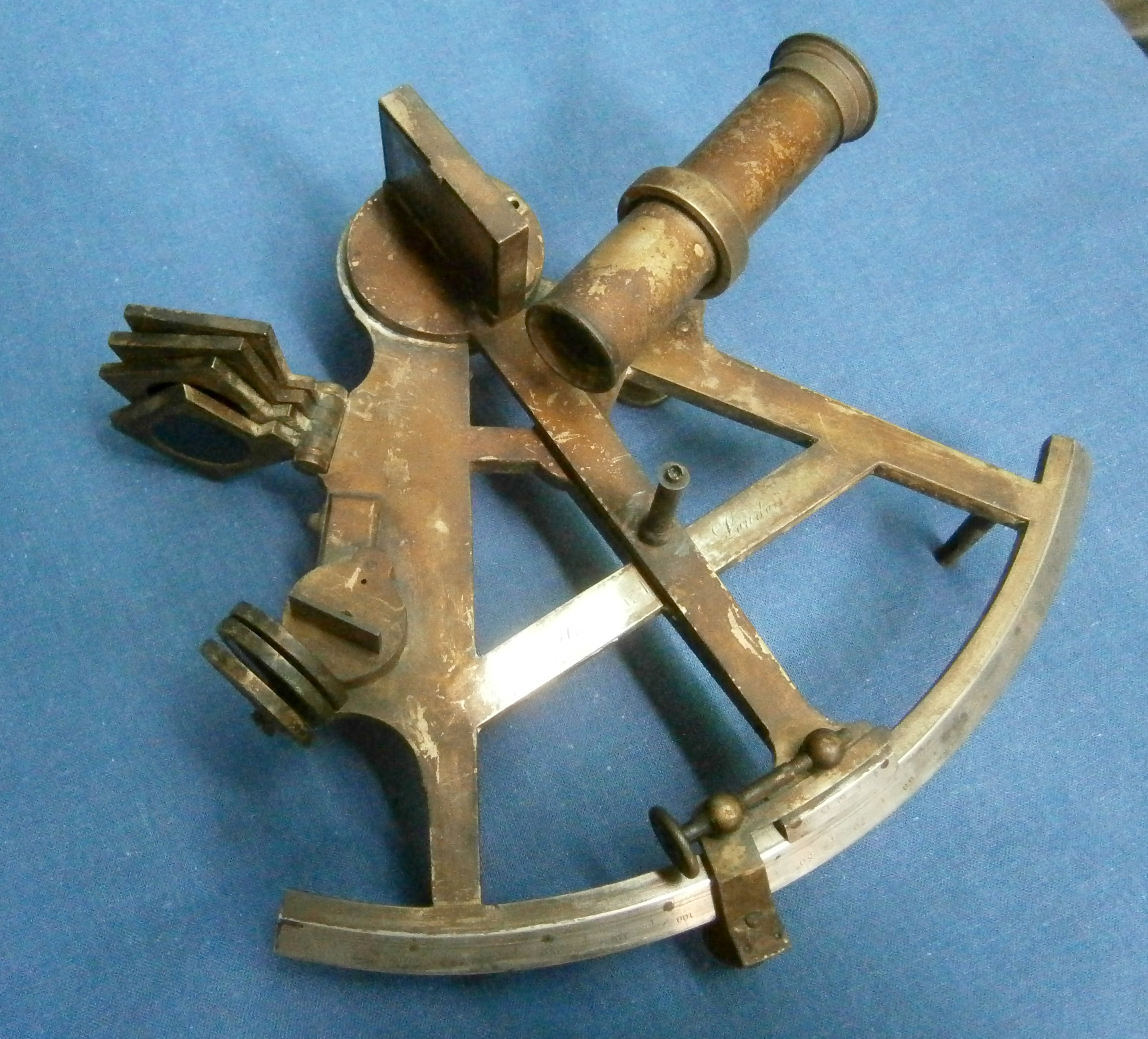
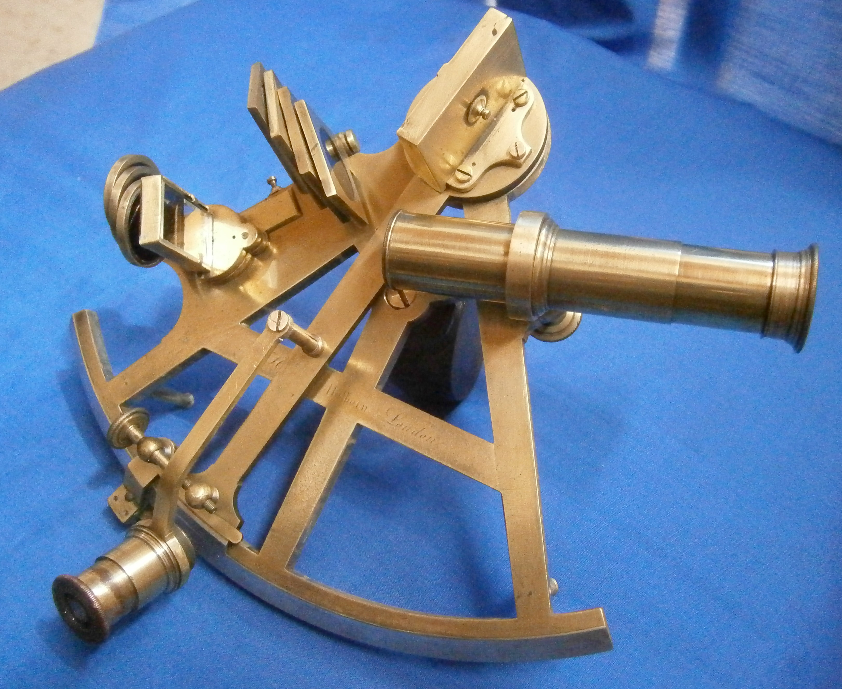
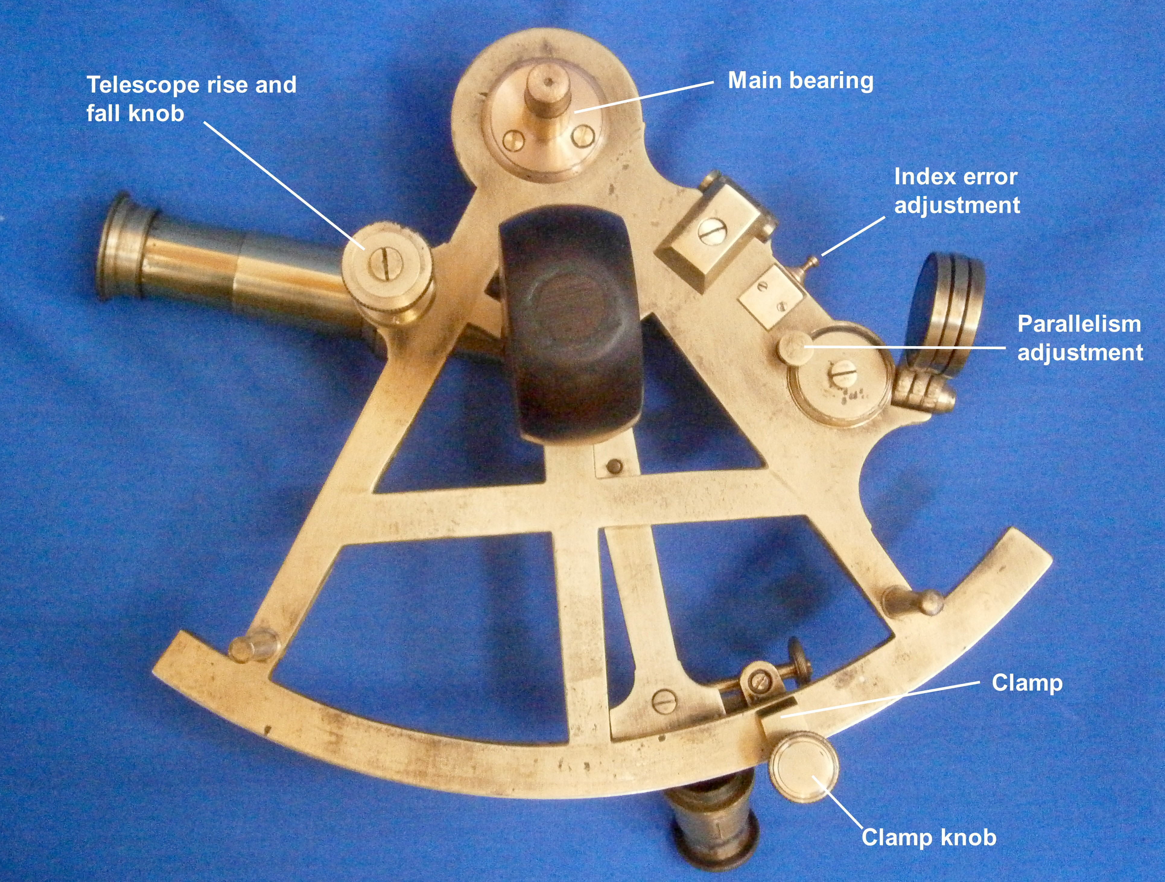
A few months ago I acquired an old sextant for a very modest price, as it was without telescopes or case. Restoration was straight forward, as all the parts were present. It was only necessary to clean and re-lacquer parts and polish screw heads and then find a new home for the instrument. Figures 1 and 2 show the general arrangement of the restored sextant from the front and back, and I have labelled the main parts for those who have not yet had the wisdom to buy “The Nautical Sextant”.
Figure 1: The sextant and its parts.
Figure 2: Rear view of sextant.
I show the naked frame in Figure 3. It is slender by modern standards, but seems to be rigid enough for its purpose.
Figure 3: The naked frame restored.
I believe that this is a relatively early sextant, based not only on the name engraved on the limb but on several other factors. To take the name first, it is “J Watkins Charing Cross London”. This must refer to Jeremiah Watkins who succeeded his uncle, Francis Watkins (1758 – 1810) in 1784 at the age of about 26 years. I have been able to find only one other sextant with J Watkins’ name on it (sold in London in 2014) and I suspect that he was the retailer rather than the maker. It was common practice for sextants, chronometers, clocks and the like to be sold un-named, for the retailer to add his name. The main activity of Watkins senior and junior, and later Watkins and Hill, was in making telescopes with achromatic lenses.
Figure 4: The name.
Looking closely at the name (Figure 4a ), the second “s” in “Charing Cross” is the old English long s, with a nub on the left of the descender. This form of s had fallen into disuse in printing by 1800 and its use here suggests the engraver had trained well before 1800.
Figure 4a.
The brass limb was attached to the hard bronze frame by countersunk screws whose heads were then filed off flush, and the ghost of one of these screw heads can be seen above the “n” of Charing Cross. Rather unusually, the divisions are made directly into the brass rather than into a band of silver let into the brass, a practice established well before 1800. The usual explanation for this practice is that brass of the time contained hard spots which could have diverted the scriber of the dividing engine from its true path and that lines on brass tended to be ragged. However, this may have applied only to English brass, as makers preferred if they could to import high quality “Dutch” brass from near Aachen in Germany.
Figure 5: Magnified view of scale divisions.
A close up view of the divisions (Figure 5) shows them to be perfectly regular, so that the scale was, I am sure, machine divided. Jesse Ramsden’s first dividing engine was finished in about 1766 . It surpassed all previous attempts at accurate machine division, but he was not satisfied with it, and completed an improved version in June 1774. Around about this time he produced a sextant shown in Figure 6, with a frame very similar, if not identical to my Watkins’. By 1789 there were three dividing engines in London, By Jesse Ramsden, John Troughton and John Stancliffe, and by 1808 there were perhaps a dozen.
Figure 6: Sextant by Jesse Ramsden.
This suggests to me that the two sextant frames had a common source in a specialist foundry and we know that Ramsden used specialist founders when he needed castings. The finish is very regular and there is no signs that it was sand cast. More likely is that it was cast in bell metal (a bronze high in tin) by the lost wax method.
The radius of the arc is nine inches (229 mm) and by 1800, because it had by then become possible to divide small radii more accurately, the more usual radius was around six and a half inches (165 mm). Thus, these several features lead me to suppose that the sextant was made some time after 1774 and before 1800.
The telescope ring and rising piece are of a form that remained common well into the twentieth century. The telescope is held in a ring that can be adjusted so that the axis of the telescope is parallel to the frame, while the whole can be raised or lowered on its square rising piece by means of an internal captive screw and knurled knob (Figure 7).
Figure 7: Telescope ring.
Compared to later sextants the index mirror is unusual in that there is no provision made for adjusting it to be at right angles to the plane of the arc. In some sextants of this era, of the three large screws seen in Figure 8, only the two outer ones attached the bracket to the index arm, while the central screw was threaded into the bracket and its tip bore on the face of the index arm, so that it was possible to rock the bracket a little to adjust it. In this sextant, the bracket was simply made square in the first place.
Figure 8: Index mirror bracket.
Figure 9 shows the front of the bracket and two of the three nubs or nipples on its face, against which the mirror was held by a clip with three tongues opposite the nubs. When the small central screw seen in Figure 8 is tightened, the mirror is held strain-free to the bracket by the clip.
Figure 9: Index mirror clip and bracket.
The index arm bearing is shown in Figure 10. It is of the form used by almost every maker until late in the twentieth century. The index mirror is attached to a disc to the underside of which is attached a tapered journal which runs in a corresponding hole in the index arm bearing. The fit is adjusted by means of an axial screw via a washer. The washer has a square hole in it that fits over a square on the end of the journal. This prevents turning forces from being applied to the screw and loosening or tightening it.
In this sextant, the whole is enclosed in a cover, which also doubles as one of the feet of the instrument. Many makers copied this practice, though in the twentieth century, when two World Wars required quantity production, it was often omitted.
Figure 10: Index arm bearing.
The method of adjusting the position of the index arm is shown in Figure 11 and is typical of the practice used in practically all vernier sextants until the last were produced in the late 1930s. A block is able to slide in a guide fabricated on the rear of the index arm expansion and the block carries a bronze nut, which sometimes has an adjustable split in it to ensure a close fit upon the tangent screw. Running in the nut is the steel tangent screw, held captive in its bearing which is attached to the index arm. Rotating the screw can move the block in its slide, but in practice, once the position of the arm has been roughly set by sliding the index arm by hand, the clamp screw clamps the sliding block to the limb of the sextant. Then, when the screw is turned, it is the index arm that slides on the block.
Figure 11: Tangent screw.
Figures 12 and 13 show the methods for adjusting the horizon mirror. The mirror bracket sits atop two circular tables. The top one may be tilted against a concealed spring using the adjusting screw, shown in Figure 13, to correct for side error.
Figure 12: Horizon mirror adjustment, side view.
The bottom circular table may be rotated through a small angle to correct for index error, using two capstan headed screws that lock against each other. The screws bear on a tongue which is an extension of the frame and the table rotates about an axis which passes through the frame and is secured by the large screw underneath.
Figure 13: Horizon mirror adjustment, rear view.
This rather complex arrangement is used on several sextants of this era. The sextant described in my post of 10 November 2009 shows an identical system, while another , shown in the post of 10 June, 2010, has a different though equally complex system. Before long, the much simpler method came in, of screws bearing against the back of the mirror with springs opposing the movement against the front of the mirror. However, some makers persisted with unreasonably complex systems of adjusting the horizon mirror well in to the twentieth century. Brandis was one late C19 maker whose system was copied for the US Navy Mark II sextant of the 1940’s and I have illustrated it in Figure 9 of my post of 30 November 2010.
Like many sextants that I can afford to buy, this instrument lacked a case. For the last nine years, I had been hoarding a case that had housed a pillar sextant. Usually, sextant cases are of mahogany, not brass-bound rosewood, indeed, this is the only example I have ever seen for a proper sextant, rather than the decorative so-called reproduction ones from the Indian sub-continent. Figure 14 shows how I have adapted the case for my Watkins sextant. Originally, it would probably have lived in a keystone case, which are difficult to make and difficult to carry. I had two contemporary telescopes saved against the day when I would acquire an antique sextant without any and had only to do a little screw-cutting on the lathe for them to fit in the telescope ring.
Figure 14: Sextant in new home.
This completes my one hundred and third blog post on sextants and, while I have material for two more, I will then have run out of subjects. I am open to suggestions about further subjects. If you have a particularly interesting sextant I would be happy to consider a guest post, though I would reserve the right to edit it if necessary. If you are interested in things navigational, don’t forget to have a look at my other site: http://www.chronometerbook.com
A little while ago I acquired yet another sounding or survey sextant for a relatively small sum. It is based on a Cassens and Plath nautical sextant. As with most sounding sextants, it has no shades, but where the index shades would normally be mounted is a leg and where the horizon shades would be mounted is a bracket for a pentagonal prism or “penta prism”.
Over two hundred C&P surveying sextants were obtained by the US Coast Guard Service from Weems and Plath around 1978, provided with a handle that would make holding the instrument horizontally easier and stripped of the lighting system, to save unnecessary weight. In my instrument, which bore a USGCS label, the lighting system is intact and there is no provision for a modified handle.
Figure 1 shows the state of the instrument as received and it had plainly not been well loved in the autumn of its life (by the way, the hand holding it is not mine).
Figure 1: C & P Sounding sextant as found.
My usual method is to strip the sextant down to the last screw and washer and then to clean and repaint everything, stripping all the old paint off if necessary. As I go, I fix electrical faults, renew wiring, replace mirrors , clean optics, and re-grease moving parts. As I have elsewhere in the blog described these activities, I will not go into them here, but instead focus on the main point of difference from other sounding sextants: the pentaprism. I have given a very brief account of the use of sounding sextants in the post for 26 April, 2009, and this should be read in conjunction with the comment kindly sent by Peter Catterall.
In a pentaprism, the emerging ray is at right angles to the incident ray, and the angle between the two rays (really two parts of one ray) is independent of any rotation of the prism about an axis parallel to any of its faces. The image is not inverted or reverted. However, if the prism is rotated about another axis, the incident and emergent rays will not be at a right angle. Although there are two internal reflections in a pentaprism, they are not total internal reflections as, say, in a 90 degree Porro prism, and so the reflecting surfaces have to be silvered. If the paint film and underlying silvering gets damaged, the damage will be apparent in the view through the prism.
Figure 2: Position of the pentaprism.
Figure 2 shows the location of the pentaprism behind the clear glass of the horizon mirror. It is located in a spring-loaded bayonet socket by means of a peg, which allows it to be placed in two positions (Figure 3). Rotating it anticlockwise locates it in the position shown in Figure 4.
Figure 3: Pentaprism base
When located in this position, if the index arm is set at 90 degrees, the two light paths should be parallel, so that a distant vertical object should form a continuous vertical, straight line when the instrument is held with the frame horizontal. For this to happen the faces of the prism must be at a right angle to the frame of the instrument, so three adjustment screws are provided to bring this about. It is a great deal easier to do this if a 2 mm diameter torus of thin, soft copper wire is placed centrally under the face opposite the adjusting screws, so as to allow a little rocking to take place. This is a little simpler than following the official advice promulgated in the US Coast Guard Service manual, available on line here:http://www.dtic.mil/dtic/tr/fulltext/u2/a059986.pdf The prism is held in place by two rectangular “springs” which offer quite a lot of resistance to the movement of the prism when adjusting it, so it is easier simply to leave them a little proud of the prism faces and rock the prism as I have suggested. The adjusting screws then do double duty of adjusting and retaining with the springs as back-up retainers.
Any index error of the sextant must of course be allowed for, in addition to any error found with the prism in place, and normal checks for perpendicularity of the index mirror and side error made and corrected.
Figure 4: Position of prism to check index error.
Figure 5 shows the prism in its orientation in normal use and you can see that with the index arm set at 30 degrees, the rays diverge by 90 + 30 = 120 degrees, the practical limit for a normal sextant, where the reflected image is reduced to a narrow slot.
Figure 5: 90 + 30 degrees = 120 degrees.
Figure 6 shows how 180 degrees can be measured by setting the index arm to 90 degrees. The ability to measure large obtuse angles improves the strength of position lines when fixing the position of aids to navigation.
Figure 6: 90 + 90 degrees = 180 degrees.
Although the stout case could be mistaken for solid wood, it is in fact some sort of laminated wood, as witnessed by the delamination of the outer layers of the top and bottom. It seems strange that an instrument destined for use in a damp and sometimes wet atmosphere should not at least use marine grade laminates for its case. The corners are keyed mitre joints which give both a very neat appearance and very adequate strength. Note that the key should be sited as close to the inside angle as feasible, as shown in Figure 7.
Figure 7: Keyed mitre joint in case.
Figure 8 shows the instrument less its telescope in its case. It cannot be stowed with the pentaprism in place, though with a little more thought, the pocket for the sextant handle could have been rotated anti-clockwise and moved to the left a little to give room for both the prism and the originally supplied prismatic monocular.
Figure 8: Instrument in its case
The telescope with my sextant is a standard 4 x 40 C and P offering except that there is a glass in front of the objective lens that acts as an astigmatiser with stars, drawing out the point sources into lines (Figure 9). It has no effect on extended images. I cannot imagine how this works, so if any reader knows, I should be glad if they would share their knowledge with me.
I hope to be able to add two or three more posts to this blog before the end of the year, after which it will the turn of a marine chronometer to be described on my other web site, http://www.chronometerbook.com .
This post was preceded by “An improvised sun compass”, ” C Plath Sun Compass”; “A Fleuriais’ Marine Distance Meter” A Stuart Distance Meter”;“A Russian Naval Dip Meter”; and “An Improvised Dip Meter”
Jaap Brinkert has kindly provided the following post . With his agreement, I have added an occasional comment in blue.
Recently, I won the bidding on a ‘Vintage Marine Sextant’ which I soon discovered to be rather unusual. At first sight, it resembles the Hughes Mk IX bubble sextant as used by the RAF (and others) during WWII (Figure 1 and 2). However, this sextant is intended for marine use. It appears that the German navy started using bubble sextants on board submarines, so that they could take sights when surfaced at night The Hughes Marine Bubble Sextant (HMBS) was the English answer, developed after tests using the Mk IX on board a submarine. {1} “Highly accurate results” seem to me to have been unlikely. One to three nautical miles would be counted good using a normal nautical sextant and the natural horizon.
Figure 1: Rear view of Mk IX A and HMBS sextants
A good general description of the device is given in “Specification of instruments exhibited at the seat of the international hydrographic bureau during the Vth international hydrographic Conference, Monaco, April 1947,” in which exhibit number. 8 of Marine Instruments Ltd, entitled “Marine Super Integrating Sextant” is described as follows. “The instrument consists of a sextant, the mechanism of which is totally enclosed with the usual fixed horizon mirror and adjustable index mirror. The mechanism is arranged to give arbitrary increments of altitude of 10 degrees, -10 to 90. Attached to the main body of the sextant by two screws is the bubble complete with eyepiece through which the observer sees the bubble and the object observed. A single instantaneous observation is made by setting the next lowest whole tens of degrees and then using the slow motion to obtain coincidence between the centre of the bubble and the object, reading the altitudes on the tens of degrees scale and the degrees and minutes scale (instantaneous reading.
An averaging observation is made by maintaining the coincidence as nearly as possible during the one-minute period of observation between starting the clock drive and the automatic raising of the cut-off shutter, the altitude being read on the tens of degrees scale and the degrees and minutes scales (averaging).
A second bubble unit is provided, interchangeable with that on the instrument. This unit is exactly the same as the first, except that it carries a 2X Galilean telescopes mounted in the unit itself, which, when sea conditions permit, gives brighter star images than would otherwise be obtained.
Two dry batteries and two spare lamps are supplied.”
Figure 2: LHS of Mk IX A and HMBS sextants.
The Marine Bubble sextant has an entirely different mechanism for averaging, which is contained within the main body, where it is protected from salt spray. It is a continuous integrating mechanism, which runs for one minute. The adjustment of the index mirror also sets the transmission ratio between a slender cone, driven at constant speed by a spring mechanism, and a cylinder connected to the totaliser (Figure 3).
Figure 3: Integrator mechanism.
This is in effect the reverse of the mechanism used in the German SOLD and Kreisel (gyro) sextants, where the inclination of a roller that bears on a shaft moving longitudinally, variably rotates the shaft, on the end of which is attached the read-out. Full details may be found in the post for 4 November 2013 . After the one minute run, the average position of the index mirror is read from a dedicated dial, and added to the setting of the index mirror, for instance 70 +4 35′.
The averaging device for the Mark IX A aeronautical sextant sampled one sixtieth of the reading every two seconds for two minutes, in effect integrating the reading over sixty intervals. The potential disadvantage of this is that if the sampling interval happens to coincide with the approximate frequency of rolling of the vessel, large errors may be introduced. The HMBS, like the SOLD and Kreiselsextant, continuously integrates the reading.
The calibration record (Figure 4) is interesting as it illustrates the consequence of a difference in timing mechanism between the SOLD and the HMBS. The former contains a “proper” clockwork with balance wheel and escapement. The latter, on the other hand, contains a regulator mechanism which uses centrifugal force and friction (if the regulator turns too fast, it ‘expands’ against a stationary drum, resulting in deceleration). This mechanism needs to be calibrated. The certificate shows a deviation of up to 1%, depending on the set angle). A small error in counter reading follows automatically. The calibration also shows the separate extra corrections for the two bubble units. Using this sextant requires quite a bit of bookkeeping!
As for a normal sextant, the HMBS has a conventional set up, except for the placing of the shades (Figure 5).
Figure 5: Front view, showing mirrors
The index mirror is rotated on a shaft which emerges from the main housing, and is operated by a mechanism described below. In operation, this mechanism is similar to that of the Mk IX series. There is a large step setting in tens of degrees (-10 (“D”) to +80 ) and a fine setting ( 0 0′ to 14 50′ in 1.5 turns of the adjusting wheel). The index mirror is quite large: 70 mm by 27 mm. Another difference between the Mk IX and the HMBS is the horizon mirror: it has no ‘5 degree increase’ facility, which also simplifies the read out mechanism for the averager. The horizon mirror of the HMBS is fixed; the whole nearly 15 degree range is set by the mirror fine-setting control. The Mk IX index mirror is the same length but only 24 mm wide. In both sextants, the length of the mirror is required because the axis of rotation of the mirror is quite far behind the mirror in order to accommodate a central helical spring and concentric shaft mounting (Figure 6).
Figure 6: Index mirror mounting.
The fixed mirror, on the other hand, is small, only 28 by 20 mm. It is fully silvered, so if the natural horizon is used, it must be viewed past the horizon mirror. In my sextant, both mirrors have deteriorated over time, so I plan to replace them with the help of the local glazier and optician.
There are three small shades (18 mm diameter transparent area). Both the horizon and the index mirror are equipped with two adjustment screws on opposite corners, in the usual fashion. In order to use the natural horizon, it is necessary either to use no shades, or to remove the bubble unit, because the shades, small as they are, cover the whole view. A sun sight using the horizon is therefore not possible with the bubble unit in place, and in any case the instrument would not normally be used in daylight with the natural horizon available..
The aim seems to have been to produce a waterproof device, and this is clear is clear from the fact that to open the main housing, 11 screw must be undone. The separate bubble scope’s lid is fastened by no less than 17 screws. Indeed, the internals looks as if they left the factory yesterday.
Shutter
As in the MkIX series, a shutter cuts out the view unless the integrating mechanism is fully wound or running, to signal to the user that the one minute integrating run is over. The user could then immediately look at his watch on the inside of his left wrist or, more likely on a submarine, call out to an assistant to mark the time. In the Mk IX series, the left wrist was illuminated via a prism in the right hand side handle but this ingenious system which also projects a beam to each of the read-outs using a single bulb, is only partly used in the HMBS. Instead, the handle is attenuated and the prism and some holes omitted. One of the several remaining holes for the lighting of the scales is visible in Figure 5.
Figure 7: Controls and read-outs.
A winding lever primes the integrator by ten strokes of the lever shown in Figure 7 and the integrator is started by operating the lever seen below the ten degrees adjustment knob. As in the Mark IX series this latter is pushed in against a spring load to rotate through ten degrees steps, governed by the three groups of holes seen in Figure 6. Further adjustment is by rotating the fine adjustment knob. Two windows give the instantaneous readings of the altitudes in tens and one degrees, and minutes are read from a further window. A fourth window behind the handle gives the integrator readout, which must be added to the tens of degrees shown in the top window.
The bubble unit
The unit, which is apparently taken directly from the Mk IX series, is attached to the main body by two screws. It contains the bubble mechanism, a partially-reflecting mirror and a mirror/lens assembly (Figure 8). There is a slanted clear glass window on the front and a clear glass window at the rear for the eye.
Figure 8: Interior of bubble unit.
The principle of the bubble unit is shown in Figure 9. The bubble is lit by daylight or a bulb via a Perspex do-nut directly below the bubble chamber. Light rays, shown in yellow, then pass through a partially reflecting glass (shown in white) and are reflected by a mirror-lens combination whose focal length is the same as the radius of curvature of the top of the bubble unit. The bubble is in the focal plane of the mirror-lens, so the reflected rays emerge as parallel rays and are reflected into the eye via the partially reflecting glass. Rays, shown in red, from the observed body via the fixed “horizon” mirror pass straight through the partial reflector. Effectively, the body and the bubble then both appear together at infinity at the eye.
Figure 9: Light paths in bubble unit
Despite the complexity of the sextant, and thanks to the use of a light alloy for all housing parts, the weight is just over 2 kg (2045 g) (including batteries). The German WWII Kreiselsextant (Gyro sextant) weighs by contrast 3 kg.
Lighting.
The bubble unit contains a light bulb and a simple intensity regulating mechanism. A strip with a vee-shaped slit, which is placed between the light bulb and the bubble unit, is moved up or down using a knurled wheel, seen labelled in Figure 8.
The left handle of the sextant is a battery holder for two C size cells. The rotary switch is operated by the left thumb. Turned clockwise it activates the bubble lighting and turned the other way lights the readouts as noted above. The bulb socket for the latter ought to be in the right hand side handle, but it is missing on my sextant.
Box (Figure 10)
The box is made of solid mahogany, and has a stout leather strap over the lid, which can be used to carry it. There are green felt covered blocks to immobilise the sextant. There is a similar arrangement for the spare bubble/scope, which is secured by two keepers (one of which was missing). There are two battery holders, which are obviously intended for the now obsolete Eveready No 8 (3 V). When two batteries of size C are stored in each holder, the lower ones can only be removed by holding the box upside down.
Figure 10: HMBS in its case.
History
I do not know the recent history of this sextant. It was donated to a Sea Scout group and sold on eBay to raise money. Its production date could be close to 1949, judging from the serial number (123).The National Maritime Museum at Greenwich has a Marine Bubble Sextant with serial number 114 with a certificate by Henry Hughes & Son dated 3 March 1949.
The certificate of my sextant is dated 18 July 1978, issued by Fenns, Farnborough Ltd. The sextant is also marked FEN/R/7/75. Fenns did the calibration of the instrument for the Air Ministry, so it appears the sextant was still in the care of the Air Ministry in 1975. Whether it was also in use is impossible to say. It seems likely that the sextant was sold sometime after 1978 and perhaps used at sea, as some external parts have corroded. However, this could also have occurred in humid storage conditions.
Concluding remarks
My impression is that the Hughes Marine Bubble Sextant was a product that was developed just too late to play a role in WWII, and which was unsuccessfully marketed after the war. Online, there is evidence of fewer than ten individual examples, two of which are in museums, three in past auctions and two in unrelated accounts. Some of these could even be the same. The two serial numbers I know are 114 and 123, which doesn’t tell much. This sextant used parts from the Mk IX (bubble unit, handle, general lay-out), but contains a completely new integrating mechanism. This mechanism may have found use in later aircraft or submarines sextants of the periscope type. It is clear that a lot of effort was put into designing and producing this sextant, so it must have been a disappointment for the manufacturer. Nevertheless, as a nautical sextant, it deserves a place on this blog. I have found a number of reports and articles on the internet which mention this sextant, but I’d like to hear from anyone who has more information.
If you enter this in the “Comments” section (below), I will forward your information to Jaap.
End note: [1] “Another enterprise of Plaskett and Jenkins was entirely successful in itself- the demonstration that the bubble sextant could be employed to aid the fixing of position of a submarine surfacing only at night when the sea horizon is invisible. Pleskett obtained highly accurate results from observations made on board a submarine off Start Point. As a result the ‘Hughes Marine Bubble Sextant’ made its appearance in 1944 and underwent trials, but apparently it never actually went into service.” (Biographical Memoirs: Harry Hemley Plaskett (5 July 1893 – 26 January 1980), Biogr. Mems Fell. R. Soc. 1981 27, 444-478, published 1 November 1981)
Readers who own a Mark IX series sextant who would like to know more about its construction, operation and restoration could do worse than buying a copy of my restoration manual. . See “My Bubble Sextant Restoration Manuals” for details.
I recently acquired for a relatively modest sum the three-circle vernier sextant shown in Figure 1. Attached at the front corner of the frame is a plate engraved with the letters “S.H.” or “Service Hydrographique (de la Marine)” or French Naval Hydrographical Service, formed in 1886 as successor to the “Dépôt des cartes et plans de la Marine”, founded in 1720. The plate seems to serve no other purpose that I can think of than as an identifier.
Figure 2: Front of the tangent screw mechanism.
Engraved on the front of the tangent screw mechanism is the name “E. Bouty”. Edmond Bouty (1845 – 1922) was a physicist in the Science Faculty at Paris, but I cannot find that he was an instrument maker, nor is there any other name on the sextant. It may be that his contribution was the design of the scale lighting system, about which more later. It is not even clear that the sextant is of French manufacture, as at the left end of the limb are the letters “D.S.” indicating Deutsche Seewarte, the German Hydrographical Service, but the frame, of about 180 mm radius, differs in detail from that of C Plath’s Dreikreis sextant.
Figure 3: Turning marks on front of frame.
The bronze frame is of no particular interest except that when clearing old and perished paint from the frame during restoration I noticed marks (Figure 3) that showed that it had been faced in a lathe, giving a small clue to the manufacturing process.
Figure 4: Spring box detail.
Returning to the tangent screw mechanism, the spring box is shown exploded in Figure 4. A tongue on the sliding block is trapped between the end of the tangent screw and a long spring mounted on a guide and retained by a nut. The end of the guide can be seen on the right of Figure 2.
Figure 5: Exploded view of index arm clamp.
The sliding block is retained in its slide in the lower end of the index arm by the retaining spring on the upper right of Figure 5, while the clamp screw and its leaf spring bears on the back of the limb. In use, the clamp is slackened and the index arm moved approximately into position, when the clamp is tightened, thus fixing the sliding block to the limb. Turning the tangent screw thus moves the index arm about the sliding block against the pre-load of the helical spring as a means of fine adjustment. In truth, it is the index arm that slides rather than the sliding block, but as no one else had given it a name, I decided to do so when writing “The Nautical Sextant.” This system of applying pre-load was used in many vernier instruments such as vernier theodolites and gun aiming systems. as well as in several makes of sextant.
Figure 6: Index mirror bracket.
The index mirror is held against a vertical bracket by means of a clip which is tightened against the bracket by means of a screw bearing on the back of the bracket. The mirror is made perpendicular to the arc of the sextant by a system that seems to have been used only by French makers. Two screws attach the radiused feet of the bracket to the upper end of the index arm and the end of a screw held captive in the base of the bracket can then rock the bracket to bring the mirror square to the plane of the arc..
Figure 7: Horizon mirror bracket.
Figure 7 shows a somewhat similar method of adjusting out side error of the horizon mirror, but in this case a deep slot cut nearly through the base of the bracket gives flexibility to the the adjustment by means of another captive screw.
Figure 8: Horizon mirror detail.
The detail shown in Figure 8, as well as making clearer how the mirrors are held against their brackets, shows that the horizon mirror bracket can be adjustably rotated about an axis vertical to the plane of the sextant, in order to adjust out index error. Note that the mirror is fully silvered, which means that the direct view of the horizon does not pass through glass and that the edge of the silvering of the mirror can be given better protection against corrosion. It does however result in a smaller area of overlap of the direct image of the horizon and the reflected image of the observed body when using a Galilean telescope. Enter “Freiberger yacht sextant” in the search box at the top of the page for a discussion of why this is so.
Figure 9: Detail of index error adjustment.
Figure 9 gives more detail on the index error adjustment. There is a boss as an axis on the underside of the horizon mirror bracket that passes through the frame and is held by a retaining screw. A further boss passes through a clearance hole in the frame and has an internal thread tapped in it as a nut. The index error adjusting screw, held captive in the frame by a screw and clamp, engages with the “nut”, so that when the adjusting screw is turned, the whole mirror bracket rotates. When adjustment is complete, the bracket is locked in place by a clamp screw..
This is a rather complex means of adjustment of the horizon mirror, which had long been achieved much more simply by means of a pair of screws bearing against the back of the mirror, while lugs on the mirror clamp provided spring loading. Elegant though it may have seemed to its (?) French inventor, it is unnecessarily complex., though perhaps no more complex than the solution adopted by Brandis and its US successors.
Figure 10: Interior of battery handle.
This sextant represents perhaps one of the earliest ones to light the scale in poor light. Scale lighting had to wait for the development of suitable dry batteries in the 1890s and of miniature flashlight bulbs with robust tungsten filaments in about 1904.
Figure 9 shows the interior of the Bakelite handle which accepts a 3 volt 2R10 battery. A screw at the lower end holds the negative pole of the battery firmly in electrical contact with the frame of the sextant and at the upper end a spring loaded switch plunger makes contact with the positive pole. The top end of the lid is bevelled and the lid itself is slightly bowed, so that when rotated closed it remains in place.
Figure 11: Wire from handle to foot.
A wire passes from the body of the switch to the foot (Figure 11), inside which is a spring loaded brass plunger (Figure 12).
Figure 12: Inside of foot.
The index arm journal is hollow and a wire passes up its centre to an insulated contact on the end, to make electrical contact with the contact inside the foot (Figure 13).
Figure 13: Insulated index arm contact.
The other end of the insulated wire passes down the index arm in a machined groove to a clip held on an insulator block (Figure 14).
Figure 14: Lighting bulb holder.
The clip makes contact with the outside of the bulb holder and thence to the central contact on the bulb. The outside of the holder is insulated from the brass interior, which is threaded for the bulb. The brass interior fits snugly in the cylindrical shade which is attached to the index arm and hence the frame, thus completing the electrical circuit. Most subsequent makers contented themselves with a simple loop of insulated wire to conduct electricity to the bulb, but this more complex and no doubt more expensive system has the merit of not flexing any wire. Like most complex systems, however, there is more to go wrong.
Figure 15: Rising piece.
The telescope rising piece (Figure 15) is simpler than that of many of its early 20th century competitors and it has a rectangular mortice machined in its face to engage closely with a tenon on the telescope bracket, so that it can be slid up or down to vary the amount of light from the horizon entering the telescope. Collimation is standard, by means of a tilting telescope ring held in place by two screws.
Figure 16: Shades mounting.
The shades make none of the usual provisions to prevent movement of one being transmitted to its neighbours. Resistance to rotation is given by means of a Belleville washer, a conical washer with the characteristics of a short, stiff spring. Since these date from about 1870, they add no clues to the age of this sextant.
Figure 17: Telescope kit.
The kit of telescopes shown in Figure 16 is for the most part standard, with a 4 x 24 mm Galilean “star” telescope for general use and a 6 x 16mm Keplerian “inverting” telescope. By the twentieth century, this latter probably received little use except for artificial horizon sights to rate chronometers in out-of-the-way places of known longitude. The large 3 x 36mm Keplerian telescope is of interest as it has a wide angle eyepiece with an eye lens of 25 mm aperture. This gives an image nearly as bright as the 4 x 24mm telescope (the extra lens in the eyepiece causes some loss of light) and with a field of view about four to five times wider.
Figure 17: Case exterior.
The mahogany case was much battered and stained, and with several shrinkage cracks, so it was gratifying to be able to restore it to the state shown in Figure 17. It looks decidedly English and placing the handle on the side follows Henry Hughes and Son’s practice, but neither the sextant frame nor the mirror mountings are consistent with this.
If you enjoyed reading about this sextant, you may also enjoy reading my “The Mariner’s Chronometer“, also available via Amazon.com.
Figures 5, 6, 12, and 13 may be enlarged by clicking on them.
During the Battle of the Atlantic, which for Britain began on 2 September 1939 and ended on 8 May 1945, without a break, Britain was nearly brought to its knees by submarine warfare. The battle began to turn away from Germany’s favour in mid-April, 1943, when for the first time convoys could receive continuous air cover between Britain and North America. It soon became apparent from increasing submarine losses that German submarines could no longer safely remain surfaced during daytime. While the Schnorkel ventilating tube mitigated this problem to some extent, by early 1943, the protection given by darkness was removed by the Allied development of airborne centimetric radar and the Leigh Light which illuminated the sea for attack once an aircraft had been guided to the submarine by radar.
In spite of having a Schnorkel, a submarine still had to surface to make observations of the stars, moon and planets at night, but as the horizon is generally not visible at night, an instrument with an artificial horizon had to be developed. I have described the SOLD KM2 bubble sextant in my post of 5 November, 2013. Unlike a large aircraft, which has at least partly predictable oscillations in flight, anyone who has taken a bubble sextant to sea will know that the accelerations as revealed by the bubble vary wildly and unpredictably. If the instrument is provided with a read-out that integrates observations over two or three minutes, as is the C Plath SOLD, it may be that results will be better than with instruments that simply average many observations at an interval that may coincide with the frequency of, say, rolling of the submarine. This potentially can lead to very large errors indeed.
When a bubble sextant is subject to an acceleration, all the fluid in the spirit level is affected. As you will see when I describe the gyro unit, when the Kreiselsextant is subject to an acceleration, the only connection between the sextant and the gyro is via its low friction, small area bearing. Effectively, the gyro is almost detached from the sextant and retains the direction of its axis of spin in space.
Figures 1 and 2 show the left and right hand sides of the Kreisel sextant. Apart from the gyro unit and minor changes to the light path, it is almost identical to the SOLD sextant, so I will describe only the gyro unit and the consequent light path changes in what follows. Readers interested in the interior of the instrument may consult my post of 5 November 2013.
Figure 1: Left hand side.
Figure 2: Right hand side
Figure 3 shows the gyro rotor sitting on it bearing in the bearing housing. The upper part is cross bored on a diameter, one end of which carries a collimating lens and the other a graticule at the focus of the lens, so that light rays emerging from the lens are parallel. When viewed, the image of the graticule thus appears to be at infinity. The lower part has 35 crescents, or buckets machined into its edge, so that when air is blown into them the rotor is caused to rotate. As the gyro rotates at hundreds of time a minute, the image projected into the sextant flickers only a little.
Figure 3: Gyro rotor on its bearing.
Figure 4 shows the image obtained of the graticule when viewed through the collimating lens. The central pair of lines are intended to be used for star observation, while the outer pair are used for moon and sun observations. The out-of focus vertical dark line is of course the central bearing spindle.
Figure 4: Graticule seen through collimating lens.
Figure 5 is a cross sectional drawing of the rotor and its housing, copied from a British analysis of the sextant reported in August, 1945. I have added the light path, The rotor has a hard steel spindle through its centre coming to a point of 0.13 mm radius. Together with a concave artificial sapphire of 3.7 mm radius, it forms a low friction, self-centring bearing for the rotor. The carrier for the sapphire is spring loaded within a lifting tube that can be raised to lock the rotor against the top of its housing.
Figure 5: Sectional drawing of gyro.
Figure 6 shows details of the gyro bearing and the lifting tube used to lock the rotor.
Figure 6: Gyro bearing detail.
Figure 7 shows the window through which rays exit the rotor into the body of the sextant. Circled in white are two of the six tiny holes or nozzles through which air is projected into the buckets at high speed at about 40 degrees to tangential to make the rotor rotate at high speed. They are 1 mm in diameter.
Figure 7: Detail of interior of housing.
Air enters the nozzles from a gallery which is connected to an air inlet shown in Figure 8 below. The air leaves the gyro housing through 8 holes drilled in the circumference of the bearing housing. A flap covers a viewing window through which the motion of the gyro may be viewed to check when it has settled into a steady motion.
Figure 9: Exterior of gyro unit.
Figure 10 shows the lamp carrier for the gyro unit. It screws into the gyro unit. When I bought the sextant it came with three 3 volt bubs with the miniature bayonet base shown, all unfortunately defective. In this voltage they now seem to be unobtainable, but I was able to find some 6 volt versions, perhaps the last dozen on the planet, and had to make up a makeshift 6 volt battery pack that would fit into the sextant in order to try it out (Figure 11).
Figure 10: Detail of gyro lamp carrier.
Figure 11: 6 volt battery pack in place
Figure 12 is of another drawing from the British 1945 report, showing the full light path. After being collimated at the rotor the image of the graticule is, I think, reverted by a pair of lenses, one applied to the face of a 90 degree prism and the second beyond a fixed mirror. This second lens appears to be at the focus of a further collimating lens that brings the rays parallel again, to be viewed in a Galilean telescope. (I am not confident that I have correctly described the function of the lenses between the two collimating lenses. If any reader can enlighten me further I should be glad to hear from them in the “Comments” section.)
Figure 12: Light path through sextant.
Figure 13 shows the instrument in its case. At top left is a carrying handle used to carry the instrument up through narrow confines of the conning tower hatches. Although it would not normally be used in daylight with a natural horizon, it is nevertheless provided with a set of four shades so that daylight observations of the sun or moon could be carried out on the uncommon occasions when the bodies are visible but not the horizon, e.g. in ice. A light shade would be needed for night observations of the moon when near full.
Figure 12: Sextant in its case, with accessories.
Below the shades is a charging adapter and blue bulb used as a dropping resistance to allow the white nickel-iron-alkali battery to be recharged from a 110 volt direct current supply. Proceeding clockwise, there is a spare gyro bearing and a bank of four spare bulbs. The sextant is held in the case by a bracket that folds down from above, which is then locked in position by a transverse bar. The sextant itself weighs just over 3 kg, but with its case it is a hefty 8.6 kg.
Figure:13 Instructions
The instructions, pasted to the inside of the lid, are of course in German, and there appears to have been at least two versions. It seems that the instrument in its case was to be set down on a table with the lid open and horizontal. An air supply probably from a foot pump, was then attached to the air inlet and pumped rapidly until the whirring of the rotor reached a high pitch, when the rotor was then allowed to settle down for three minutes, though this appears later to have been altered to five minutes. During this time, precession of the rotor settled down so that its vertical axis was aligned with local gravity, and the light path through it horizontal. The integrator was then wound up, the instrument eased carefully out of its case and the carrying handle clipped into place (Figure 14), all the time keeping the sextant upright and avoiding knocks or sudden movements.
Figure 14: handle in place.
Even removing it from its case needs great care, as it is a narrow fit and it is all too easy to catch it on some projection. The sextant is then passed from hand to hand up the conning tower, all the time avoiding sudden movements and knocks. On reaching the top, the handle is then unclipped. The spring is strong and again it is quite difficult to do this without upsetting the gyro. The main switch on top of the left handle was then switched on and the gyro lighting control in the left handle (Figure 1) adjusted and a view of the graticule obtained. The gyro lighting comes on only when the integrator is wound up and goes out when the integrator runs down, signalling the end of the observation period to the observer. The lighting of the integrator read out then comes on and its intensity can be adjusted using the scale lighting control (Figure 2). Pressing the button switch on the scale lighting cover (Figure 2) causes the integrator lighting to go out and the lighting to the remainder of the scales to come on.
The cone of visibility of the graticule is quite small and it needs a little practice simply to obtain a sight of it on dry land. I imagine it would need much practice to see it and then make it coincide with a star on a submarine at sea, but we know from at least one voyage report that this was done successfully, though we do not know with what degree of accuracy. Hand held, on dry land, the mean error of 50 observations of the sun was 10.9 arc minutes, with a standard deviation of 8.86 minutes.
As spinning tops as toys have given way to electronic games at all ages, some readers might wonder how it is that the gyro comes to define the vertical with its axis and hence provide an artificial horizontal via the graticule and collimating lens. Another way of putting the question might be: why does a spinning top stand up, but this is somewhat complicated because at rest in this gyro, the rotor is stable, as its centre of mass is 3.5 mm below the bearing.
The law of conservation of angular momentum decrees that undisturbed, a rotating body will continue to maintain the direction of its axis of rotation unless a force acts upon it. The only available forces are gravity and friction in the bearing and, as I have noted above, the end of the spindle is spherical, with a radius of 0.13 mm, so that when leaning, the centre of mass does not coincide with the centre of the spindle. This with gravity creates a couple, which leads to the axis describing a cone, or precessing until the centre of mass is coincident with the centre of bearing, in which position it is upright.
Readers of a mathematical bent (which I am not), will find a more lengthy and satisfying explanation in most university level textbooks of physics and mechanics. In 1890, J Perry published an entertaining little account of a popular lecture he had delivered, “Spinning Tops,” in which the words, “vector,” “angular velocity” and “torque” do not appear. General readers may find in this a more accessible account.
Previous posts in this category include: “A C18 sextant named J Watkins”, “An Old Wooden Quadrant Restored”, ” A turn-of-the-century French sextant”, “A Half-size Sextant by Lefebvre-Poulin”, ” A Fine Sextant by Spencer, Browning and Co”, “A C19 Sextant Restoration” , “Making a Keystone Sextant Case” , “Restoring a C. Plath Drei Kreis Sextant” , “Heath Curve-bar sextant compared with Plath” , “A Drowned Husun Three Circle Sextant”, ”Troughton and Simms Surveying Sextant” , “A Sextant 210 Years On” , “A fine sextant by Filotecnica Salmoiraghi”, “A British Admiralty Vernier Sextant”, “An Hungarian Sextant via Bulgaria” , “A Half-size Sextant by Hughes and Son” and “A Fine C Plath Vernier Sextant”, “Heath and Co’s Best Vernier Sextant.” and “An Early C19 Ebony Quadrant Restored”.
Two thousand and nineteen was a busy year for me and now that 2020 is upon us I find that I have not written a post in this blog for about a year, though not for want of trying, as I see that I got as far as writing the title of this one in August, 2019, having bought the instrument in April. My chronometer blog (www.chronometerbook.com) fared a little better, with one post. I have begun to make a catalogue of my nautical sextants and related instruments, and this morning found that I had omitted to describe a survey sextant that I acquired in 2013, so I will try to write about that after this one, in between mending and rating chronometers.
Figure 1) Case exterior.
All the photographs are of the instrument after restoration. For some reason, I did not think to take photographs as I proceeded. Except for a small area of the case at the bottom right and a re-positioned hinge, the case was intact. The stepped case looks rather archaic and I have come to associate it with early American instruments, or rather, instruments sold in America. If any one knows something different, I would be glad to hear of it. Where it is un-stained, the timber is light brown, but I am inclined to doubt that it is mahogany. Again, American readers may be able to inform me.
The octant came to me missing two of its legs and its peep sight. Fortunately, I could copy the remaining leg, and for the peep sight I had a model of the pillar that I could copy from a restoration described in my post of 13 June, 2018.
Figure 2: Seller’s label.
A seller (there may have been others) was “Robert King of 219 Front Street, New York. Between Beekman Street and Peck Slip.” The hand-written address is pasted on top of the rest of the label. All these names still exist, but unless 219 was down an alley way, it has been replaced by a modern-looking frontage. Perhaps someone in New York can add information that it not available by my having looked on Google Earth. I have not been able to discover when Robert King was active as it is unfortunately a very common name. Very many instrument makers did not actually make the instruments that they sold and this applies particularly to sextants, because of the requirement for a large and expensive dividing engine. It may be that they sometimes assembled instrument from major parts and possessed enough skill to carry out overhauls and repairs.
Figure 3: Divider’s logo.
We can be sure that King did not make the frame of this instrument and it is very unlikely that he made any other parts. Figure 3 shows the central part of the arc, which has a very clear fouled anchor logo. This is usually associated with instruments divided by Jesse Ramsden after completing his second dividing engine in about 1774, with the logo flanked by the initial letters I and R. It may be that Matthew Berge, who took over the business after Ramsden’s death in 1800, continued to use the logo as a sign of excellence, though without the initials. Berge’s price list for 1801 shows him selling “Hadley’s Octants in ebony with ivory arches” for between £2 5s (£2.25) and £5 5s (£5.25). Families of the time could get by on about £40 a year and be comfortable on £100, so even a cheap ebony octant represented a considerable investment.
However, King may have carried out a repair on the octant as shown in Figure 4. An area of weakness where the index shades are mounted could have led to splitting of the ebony frame along the grain. This area has been reinforced by letting in a slip of brass, secured at one end by a screw.
Figure 4: Repair to frame.
Early quadrants, which were divided by hand, necessarily had to have large radii, of about 380 mm (15 ins), and they were not provided with a handle. My quadrant has a radius of about 290 mm (11.5 ins) and has no handle, so while the design is archaic, it must have been made in the 1770s or later. Another ebony quadrant that I have is of about 250 mm (9.8 ins) radius and has a typical handle, so is probably later.
Figure 5 shows the octant in its case with the major parts labelled for the benefit of those people who have yet to buy a copy of “The Nautical Sextant.”
Figure 5: Octant in its case
As is usual with keystone cases, the octant is a tight fit and the curved part of the case is not, as one might expect, a segment of a circle, but its radius increases from left to right, so the index arm has to be set over to the right. I have added pieces of felt at each corner to the rectangle of cork that prevents the index arm expansion from resting against the inside of the case.
Figure 6: Interior of case.
Just visible in Figure 6 is a circular piece of cork, faced with felt, attached to the lid. This sits on top of the transverse member of the frame and, with a pocket for the top leg which I have added, prevents the octant moving about when the lid is closed.
Figure 6 shows a rear view of the instrument out of its case. The frame is made of heart ebony, a hard, black, stable and very dense African hardwood. The index arm and most of the other fittings are of brass, while the arc and note pad are of ivory.
Figure 7: Rear (right hand side) view.
Figure 8 shows details of the scales. The main scale is divided to 20 arc-minutes and the vernier allows readings to a precision of 1 minute. The scales are very well preserved. Ivory tends to shrink in a dry atmosphere and often the glue that holds the main scale inlaid into the limb gives way at one end. The vernier is as usual riveted to the index arm and shrinkage often causes the ivory to crack around one of the holes.
Figure 8: Details of scales.
When wooden frames gave way to ones of bronze, ivory for the scales continued to be used in cheap instruments, rather than scribing divisions directly into a brass limb rivetted to the frame. The sextant described in my post for September 17, 2018 is the only one I have seen where this has been done. Usually, an arc of silver was let into the limb, as the pure silver was unlikely to divert the scriber like the hard spots often found in the brass of the era.
Figure 9: Tangent screw details.
The mechanism for fine adjustment of the index arm is shown in Figure 9. Releasing the “clamp” by unscrewing the locking thumb screw allows the index arm to move freely so that a body can rapidly be brought down to near the horizon. Then the S-shaped piece of metal shown here and in Figure 10 is clamped to the limb. The nut is also attached to this piece of metal or “clamp”. The tangent screw is held captive in its bearing on the right of Figure 9 and the bearing is attached to the index arm, so that when the screw is rotated the index arm is moved slowly one way or the other about a curved guide formed for the base of the clamp on the back of the index arm.
Figure 10: End view of tangent screw clamp.
A piece of spring steel protects the back of the limb from the tip of the clamp screw. What is difficult to show in either photo is that there is a short tongue projecting at the base of the “S” and this slides in a rebate on the front of the limb – except when the clamp screw is tightened.
As the peep sight was missing altogether, I had to use the pillar from another sextant as a guide to its shape, and then saw and file up the shape of the disc part from sheet brass. I then inserted the disc into a mortice machined into the top of the pillar and secured it with solder.
Figure 11: Peep sight from eye side.
The centre line of the two holes lines up with the horizontal centre line of the horizon mirror. The hole nearer the frame lines up with the junction of the plain and silvered parts of the mirror, while the other hole allows a larger view of the horizon for when its contrast is poor. The shade shown in Figure 12 can be rotated to obscure one or the other of the holes.
Figure 12: Rear of peep sight.
Flint glass was essential to make achromatic lenses, but in the eighteenth century it was difficult to obtain in large pieces, so that telescopes were not only expensive but had relatively small apertures of 16 to 20 mm.
When a sextant or octant was used only for taking the noon altitude of the sun for latitude, a peep sight was perfectly adequate for a “normal” eye, which could resolve an arc-minute, in keeping with the precision of the instrument. A normal eye is usually quoted as 6/6 vision (20/20 in the USA), but many young people have 6/4 vision or even better, meaning they can resolve detail at 6 metres that a “normal” has to be at 4 metres to resolve.
When it became necessary to resolve 10 arc seconds (one sixth of a minute) in order to measure lunar distances between the moon and the sun or stars, telescopes became nearly essential, though that great navigator, humanitarian and scientist, Captain James Cook, did not use one until his second voyage of exploration. On January 15th, 1773, he wrote in his log “…we can certainly observe with greater accuracy with the telescope when the ship is sufficiently steady which however very seldom happens, so that most observations at sea are made without…” With the wider field of view available with a good modern telescope it is easier to use one, but on my voyages aboard HMB Endeavour, which rolls a lot, I usually brought down a body without the telescope and then added the telescope to my modern sextant to make the fine adjustment and bring the body to sit accurately on the horizon.
Figure 13: Structure of index bearing.
Figure 13 shows the structure of the index bearing. Strictly speaking, it is that which encloses the journal or shaft, but loosely the word is used to include both. There is a brass washer let into each side of the frame and the two are held together by two rivets. The washers enclose a short piece of brass tubing, which forms a bearing for a plain parallel shaft attached to a large circular table on the front (left) side of the octant. This carries the index mirror. Originally, a piece of parchment separated the table from the frame. As it had fallen apart, I replaced it with a thin sheet of nylon.
On the back or right hand side a heavy brass washer with a a square hole fits closely over the square on the end of the shaft, so that it turns with the shaft without rotary motion being transmitted to the securing screw and loosening it. There is no provision for taking up wear, but as it is not an instrument of the highest precision and the shaft is lightly loaded and always moves slowly, no wear is to be expected. An old author (I forget which) made reference to what we would now call “stick-slip” or “stiction” and suggested that having achieved contact of a body with the horizon and clamped the index arm, it might continue to move a little without the tangent screw having been touched. I have never been able to observe this. It may be that the author had over-tightened the bearing.
With further development of octants and sextants, a tapered bearing was adopted almost universally, as it allowed for fine adjustment, though the narrow adjusting screw was prone to be over-tightened and broken off by heavy-handed mariners who did not understand the bearing’s structure.
Figure 14 shows the front of the index mirror and its bracket. The “silvering” was probably made from an amalgam of tin with mercury and it was coated with protective sealing wax. While I have replaced the very badly decayed horizon mirror, I have left the index mirror in place as it is still just about usable for demonstrations. The clip that holds it to its bracket is archaic as it applies pressure to three edges of the mirror. From the middle of the eighteenth century it had been appreciated by the Dollonds that to avoid straining and distortion of the glass, it should be restrained at three points only, and seated under these points on three nipples.
Figure 14: Front of index mirror and bracket.
The rear of the clip (Figure 15) has two screws that pull the mirror clip backwards so the the edges of the mirror are held against narrow raised edges of the right angled bracket. The underside of the base of the bracket is slightly curved so that it can be tilted slightly by the tilting screw so that the mirror can be brought to a right angle with the plane of the arc. This is an effective way of doing so, but if not properly understood, the thread of the tilting screw could be stripped or the base bent by a heavy-handed adjuster.
Figure 15: Rear of index mirror bracket.
The base of the index shades can be seen in Figure 3 at the top right. Figure 16 shows the shades and the base in detail.
Figure 16: Index shades.
The glass of a shads was usually held in its frame by swaging or deforming the metal over the bevelled edge of the glass, and this can be seen in the bottom two shades. In the top one, the glass seems to have worked loose and is held by antique putty which I have left in place. The shades are separated by washers and held together in a fork which can be closed up by the screw so that they do not flop around. Note in passing that the slot in the screw is vee-shaped, having been formed by a file rather than by a saw, a reflection on the expense and difficulty in the era, of working steel to make a hack or rotary saw.
The split in the base to make a spring allows the shades to be removed easily, an archaic and unnecessary feature in this instrument and presumably a left-over from the time when octants were sometimes fitted with back sights which needed the shades to be moved in position, as in the one I described in my post of June 13, 2018. A brass facing was attached to the sextant by two screws, with a slot for the shades and holes for the horizon mirror base and its adjustment (Figure 5).
The horizon mirror has a complex arrangement for adjustment. The mirror is held by the clip against a bracket in the same way as for the index mirror. The bracket lies on top of a circular base which can be tilted about an axis of two short pins or nipples by means of two screws to remove side error (see Figure 19 for the details). The base has a short tapered shaft with a square formed on the end which passes through the frame and a straight crank, to be secured by a washer on the other side.
Figure 17: Horizon mirror and bracket.
The base can be rotated through a small angle to remove index error by means of a half-nut formed on the end of the crank and a worm screw, and locked in place by a locking screw (Figure 18). The exploded view in Figure 19 perhaps makes the arrangement clearer.
Figure 18: Horizon mirror index adjustment.
When I removed one of the tilting screws it lost its head and I was obliged to make a new one. The old and the new can be seen in Figure 19, lying above the rotating base.
Figure 19: Horizon mirror adjustments exploded.
I have not illustrated an important addition to the octant, the handle, because none was provided. It is likely that this was a basic octant without frills.
You can find many details about the structure of sextants up to modern times in my book “The Nautical Sextant.” available through Amazon and good nautical booksellers like Paradise Cay and Celestaire.
Julian Thornton recently wrote to me about his newly acquired Freiberger Trommelsextant , asking about a fitting attached to the outside of the micrometer mechanism. He was able to de-construct it to get it working and kindly agreed to write a guest post. This is what he wrote (I have added comments in blue):
I bought a used Freiberger Trommel sextant on eBay and when it arrived it had an attachment on the micrometer drum (Figure 1)
Figure 1: Lighting unit as found.
At first I didn’t know what this was (this was my first sextant) but eventually worked out that it was a lighting unit. It didn’t work so I decided to take it apart. An exploded view of the disassembled lighting unit is shown below (Figure 2). This figure can be enlarged by double clicking on it. Use the back arrow to return to the text.
Figure 2: Lighting unit exploded.
The frame of the unit wraps around the micrometer housing of the sextant and is held in place by a thumb screw (see also Figure 4). The bulb screws into the bulb housing.The contact rod is insulated from the bulb housing by the insulating bush. The bush screws into the other end of the bulb housing. A screw passes through the switch arm into the end of the contact rod. The other end of the switch arm is secured by a screw which passes through an insulating bush into the right hand end of the battery housing to make contact with the battery. When bulb end of the arm is depressed, the end of the contact rod makes contact with the central contact of the bulb. The circuit is completed via the spring, cap, battery housing, frame and bulb housing into which the bulb screws.
This unit would not be too difficult to reproduce in a well-equipped home workshop. I may try to do so when I run out of other things to do...
The first thing I did was put a new AA battery in it but it still didn’t work. I inspected the bulb but I couldn’t see a filament, but as I didn’t have a circuit tester with me I could not test its continuity. On the side of the bulb it said 1.5v 0.2A so I looked online and found that E10 1.5v 0.3A bulbs are pretty common so I bought some. I also noticed that the original bulb appeared to have thicker glass of the top than the sides, almost as if it were a crude lens, see bulb on the right in the picture below (Figure 3).
Figure 3: New and old bulbs.
The old bulb with its lens is called a pre-focus bulb
I emailed Freiberger in Germany to ask about the bulb and ask if they sold spare bulbs. They confirmed that the bulb does indeed have a thicker end than sides but that they do not sell spares of any type for the illuminator mechanism, but that I could buy a complete new unit for €136 plus postage and packing. They said that a standard E10 1.5v bulb would work fine. I then cleaned up all the contacts and reassembled the unit with the original bulb. The light came on immediately and the unit worked well with the on / off function provided by pushing the metal screw at the end of the lamp assembly which then makes the electrical circuit, see LHS of end view below, Figure 4. The natural tension of the metal plate connecting the battery and lamp assemblies then moves the screw away thus breaking the electrical circuit.
This photo also makes clear how the unit is attached to the sextant.
Figure 4: End view of switch.
When the new bulbs arrived I inserted one and it came on immediately but the only way I could turn it off was to remove the battery. On further examination of the new and old bulbs I noticed that the new bulb was fractionally longer so I filed down the contact end of the bulb with emery paper and re installed it. The unit then worked properly. The new bulb is rated at 0.3A so in fact is a 50% higher power rating than the original bulb and is a noticeable improvement.
A little while ago I bought a SNO-T sextant on a local auction site, not because I did not have one (I have two), but because the price was too attractive to miss. I found there were two major and one minor problems with the instrument: one hinge had torn from the the case, one shade was a “foreigner” taken from an SNO-M sextant and the star or Galilean telescope was out of alignment. Some may not think the damage to the case to be important, but a sextant is an instrument of precision and if it is not contained safely in its case it may suffer unnoticed damage. Figure 1 shows that a cure could not be effected with filler or “builder’s bog”. I had to saw and chisel away the damage down to fresh wood and glue in a piece of close grained wood .
Figure 1: Case damage.
Figure 2 shows the result, with screw holes marked out and pilot holes for screws drilled.
Figure 2: Wood inserted
As a later photograph will show, the designs of the shades for the SNO-T and the SNO-M are very different, so I elected to make a new bracket and use the glass from the SNO-M. I began by marking out a piece of aluminium alloy plate and boring a hole to make a seat for the glass.. Rather than swaging the glass into place, I planned to use modern two-part epoxy glue.
Figure 3: Boring the shade bracket blank.
The next step was to saw the outline of the blank to shape with a piercing saw (Figure 4) and finishing by filing.
Figure 4: Sawing the bored blank to shape.
Figure 5 shows how “cheaters” are used to guide the file when making tight curves in soft metals like aluminium and brass. They are simply hardened cylinders held in place with a nut and bolt and when a gently used file begins to skate over them, the soft metal has been guided into shape.
Figure 5: “Cheating” a curve.
All that remained was to ease the glass into place with a tiny smear of glue to hold it there and paint it to match the rest of the sextant. “Hammerite” hammered grey paint gives a close match. Figure 6 shows the completed shade.
Figure 6: Completed shade on left.
The “star” telescopes of most sextants are not adjustable for collimation. The word appears to have come from the mis-copied Latin word “collineare”, to direct something in a straight line according to the Oxford Latin Dictionary. In the context of sextants, it means to direct the optical axis of the telescope parallel to the plane of the arc. Except at high altitudes, small errors are of little importance in ordinary navigation. For example at a reading of 60 degrees, a 45 minute tilt of the telescope results in an error of about 20 seconds, an amount which would normally be swamped by other errors. However, in the days of lunar distance observations and checking chronometers by celestial observations, such an error would be significant, and the higher powered inverting or Keplerian telescopes were normally provided with a means of collimation.
The easiest way to check collimation is to check that the face of the objective lens cell is at right angles to the plane of the frame of the sextant, a shown in Figure 7, where there is an obvious wedge of light showing,
Figure 7: Mis-collimated telescope
The rising piece of the SNO-T telescope is a casting that is integral with the body of the telescope and one would be ill-advised to attempted to correct the error by bending it, as aluminium castings have an unfortunate tendency to give no warning that they are about to break. Instead, it is simpler and safer to slowly and carefully file the underside of the telescope bracket, where there is usually plenty of metal, and this is what I did. Figure 8 shows that the error has been corrected.
Figure 8: Telescope collimated.
I have dealt with the rest of the overhaul in my manual on the construction, repair and maintenance of the SNO-T Sextant, which is still available for purchase (see post for 22 November 2008 for details). Figure 9 shows the instrument in its repaired case. The original colour of the case was light grey, and as it had become battered during its life since 1975, and I had some very tough gloss blue paint left over from another job, I used it on the outside, while touching up the lemon yellow of the interior and renewing the felts. The match of the yellow is not perfect, but is much better than nothing.
Figure 9: Overhauled sextant in its up-graded case.
For years I have wished to reproduce the method of re-silvering sextant mirrors using the process which was common until the mid 19th century, when chemical methods of depositing silver on to glass were invented. For several centuries prior to that, tin foil was dissolved in mercury to form a two-phase amalgam of tin-mercury crystals. A ready source of tin foil used to be tea chests, but if they exist at all nowadays, they will be lined with aluminium foil, which does dissolve in mercury but immediately decays to an oxide-rich powder.
For a sextant mirror, only a few drops of mercury are needed and high purity tin foil can be obtained in small quantities from China on e-bay. Mercury metal is fairly harmless stuff in itself, but its vapour poses health risks and many of its organic compounds are very toxic. For our purposes, we do not need to wear personal protective equipment, wear rubber or nitrile gloves as well as protective eye wear, nor do we need to use respirators with cartridges approved for use with mercury vapour, as the amount of vapour released by the tiny amount we need must pose negligible risks.
Mercury metal is a bit hard to get hold of, as many carriers refuse to handle it because of its highly corrosive effects on aluminium and often groundless health fears, but an old mercury in glass thermometer or two may contain all we need. I am fortunate to have been given a litre by a retired chemistry teacher who had received several litres of it when an old DC power station closed down.
The first step is to remove the old silvering. Classically, it was coated with sealing wax, which is mainly shellac with a colouring substance, so it can be soaked overnight in alcohol and then rubbed off with a finger. The old silvering may come away with it, but if not, it can be dissolved in concentrated hydrochloric acid, often sold as “spirits of salt” for cleaning concrete. The vapour from fuming hydrochloric acid is irritant, so cover the container while the mirror soaks. The glass can then be thoroughly cleaned with alcohol to remove all traces of oil or grease.
The next step is to smooth a piece of tin foil about the same size as the mirror with a margin of a few millimetres all round. This can be done on a smooth glass or other clean surface, using the finger tip or a scrap of chamois (“shammy”) leather (Figure 1).
Once this is done make sure it has not stuck to the glass. I then transfer it to a piece of cartridge paper with folded-up sides to catch any stray mercury.
Figure 1: Smoothed foil.
Then add a drop of mercury and spread it evenly over the foil with a finger tip to give a brightly glistening surface . Add another drop of mercury, to give an excess, which brings any dross of mercuric oxide and dust to the surface (Figure 2).
Figure 2: Mercury excess.
Then place a slip of clean paper on top of the mercury, followed by the glass and holding the glass with a light downward pressure, slide out the paper and, with luck, the dross (Figure 3).
Figure 3: Removing dross.
Tilt the glass and let excess mercury drain off ,steadying it so that it does not slide off (Figure 4). Note the brightly reflective result.
Figure 4: Draining mercury 1.
The mercury tends to collect at the bottom edge and can be encouraged to drain by adding a slip of tin foil (Figure 5).
Figure 5: Draining mercury 2.
At this point, I slide a slip of paper between the foil and the glass substrate to prevent the two from sticking together, and allow a day or so for all the mercury to drain away. Though now containing tin, it can be collected in a separate vessel and used again if one does much silvering. Figure 6 shows the back of the new mirror after trimming excess tin.
Figure 6: Mirror back.
And Figure 7 shows the front. Tin is less reflective than silver, but the eye can just about detect a doubling of brightness, and I certainly cannot detect any difference between modern mirror glass and the few ancient sextant mirrors I have renovated.
Figure 7: Mirror front.
I use acrylic paint to protect the back and continue the paint around the sides to ensure a waterproof seal. If “authenticity” is desired and you can find sealing wax you can dissolve it is “spirits of wine” (alcohol) and use that as a sealant, or colour some shellac.
A few years ago, I bought a Mark IX bubble sextant for parts from a local auction web site. I had vaguely noted an excrescence had been added to the top, and when it arrived I found that it contained a ninety degree prism. The bubble unit had been removed and in its place was a half-silvered mirror angled at 45 degrees. Someone seemed to have attempted a conversion so that the sextant could be used at sea, using the natural horizon. This in itself is not a bad idea, as the Mark IX series of bubble sextants represents a cheap way of getting an instrument with a digital read out, as shown in Figure 1.
Figure 1: Right-hand side of sextant.
The index mirror is rotated in steps of 10 degrees(actually 5 degrees but the light ray is deflected through 10) by depressing the knob and rotating it, when on releasing it it clicks into the selected value. Pushing up the 5 degree knob adds five degrees rotation to the ray deflection. The fine adjustment knob adds up to 8 degrees fifty minutes to the value set by the 10 degree knob.
Upon further exploration of the excrescence at the top it turned out to contain a right angle prism to divert light entering it directly downwards into the instrument. A variable polaroid filter can be swung to filter the incoming light. I suspect the fitting was canabalised from something like a WWII drift meter. A half-silvered mirror with a silvered aperture of only 18 x 7.5 mm diverted the down-coming rays into the eye hole, joining the rays from the observed body, as in a normal sextant.
Figure 2 shows the interior of the sextant. The gearbox, as well as counting off the degrees and minutes, also rotates the index mirror. The shades control allows seven combinations of three shades of increasing total density
Figure 2: Interior mechanism.
Figure 3 shows the light path of the conversion. Horizon rays are shown yellow, body rays are shown red and the mirror as dashed green.
Figure 3: Light path
It is not my intention to provide detailed instructions on replicating this instrument layout, as much will depend on the skills and workshop resources of the reader. However, a few details may help.
Figure 4 shows the prism mounting from the side. The prism is cemented to a back plate which is held against three points by two springs. The three points are a fixed nipple and two screws for adjusting index and side error.
Figure 4: Side view of prism mounting.
Figure 5 shows that the prism backplate lies between two guide rails, soldered to a further plate which forms the rear of the mounting and which is threaded for the adjusting screws.
Figure 5: Apical view of prism mounting.
I felt that the view through the half-silvered mirror was rather restricted and also discovered that it was not well-centred on the light rays, so I replaced the mirror and its mounting with one carrying a 50% beam splitter measuring about 25 x 20 mm. This is mounted in the left half of the instrument frame, as shown in Figure 6 with the light path.. By carefully adjusting the permanent height of the mounting above the frame I was able to get the horizon view to occupy roughly half of the field of view, while the body rays occupy the whole field of view. The horizon f.o.v. is somewhat brighter, as it has passed through fewer air-glass interfaces.
Figure 6: Beam splitter position.
For those who are not familiar with the Mark IX series of bubble sextants, the two halves mate together, located by two dowel pins and four screws a shown in Figure 7. Those interested in restoring A Mark IX, IX A or IX BM to working order as a bubble sextant will find my restoration manual a useful guide. See: My Bubble Sextant Restoration Manuals for details.
This post was preceded by “Hughes Marine Bubble Sextant”, “An improvised sun compass”, ” C Plath Sun Compass”; “A Fleuriais’ Marine Distance Meter” A Stuart Distance Meter”;“A Russian Naval Dip Meter”; and “An Improvised Dip Meter”
A little while ago I was idly reading and came across something called the Bygrave Position Line Slide Rule. Being already interested with things navigational, I started looking for more information about what this instrument was and how to use it. One thing led to another and before long I desired to make my own reproduction. To that end, I contacted Bill Morris with a request that he publish a blog post about his reproduction of the German version of the Bygrave manufactured by Dennert and Pape called the MHR1. Bill has added remarks in parentheses in italics.
(I had made the rule several years previously as a construction project and, having made it and tested it once or twice, placed it in storage.)
At the time I mostly hoped that he’d read my request and eventually write a post that covered the details of the methods he used to make his. Much to my surprise, he responded almost immediately and offered to send it to me to inspect. (For the most part, construction consisted of simple turning, sawing and filing)
I, of course, jumped on the offer. A few weeks later, this instrument arrived, very carefully packed.
Figure 1 Bill Morris’ fine work
Here are my musings that contains a little history, a little description, and a bit about using one.
Prior to the widespread introduction of modern sight reduction tables, a navigator would reduce sights by referring to books of trigonometric tables, reading them out, then adding/subtracting/multiplying them together, and then going back into the tables to extract an angle. For a 3-star fix, the amount of effort required would of course by multiplied by three. This can take a bit of time as it is a painstaking process. (When I started to take an interest in navigation more than forty years ago, in the (forlorn) hope that someone would invite me aboard a yacht for an ocean voyage, this is how I reduced my sights, using Burton’s Nautical Tables. Then sight reduction tables followed and finally I used a scientific calculator.)
The 1920s and 1930s saw aircraft capabilities in both speed and range increasing rapidly and, since aircraft can move considerably faster than a ship, a fix determined 30 minutes in the past is less helpful than a fix determined 5 minutes in the past. Thus, considerable effort by many people and institutions went into fixing the position of an aircraft more quickly.
Captain Leonard Charles Bygrave (RAF) at the Air Ministry Laboratories developed what would become the Position Line Slide Rule in the early 1920s. The motivation was to provide an air navigator a compact, lightweight, accurate enough, and fast means of solving the celestial triangle so the navigator could determine the altitude of the body (Hc) and the true bearing to the body (Zn).
The equations to solve the celestial triangle use trigonometric functions in combination. The equations themselves are shown below and were found on the following web site: Formulas (thenauticalalmanac.com).
Hc = sin-1[sin(declination) x sin(Latitude) + (cos(Latitude) x cos(declination) x cos(LHA)]
Z = cos-1[(sin(declination) – sin(Latitude) x sin(Hc)) / (cos(Latitude) x cos(Hc))]
Note that Z requires some additional, minor, manipulation to form Zn depending on the magnitude of Z and whether the assumed position is in the Northern or Southern Hemisphere but that is beyond the scope of this post.
In theory, a standard slide rule with the trigonometric functions on the face could be used to solve these equations. This method is more compact than the traditional method of trigonometric values taken from a large book of tables but still quite painstaking as each step needs to be recorded on paper, sums and products taken, additional sums taken, and then inverse trig values extracted.
Taking the slide rule idea slightly further, however, the scales of a slide rule could be created to enter assumed position and declination and then directly extract Hc and Z which would greatly simplify and speed up the process.
The problem with a linear slide rule is that, to get the required accuracy, the slide rule might be many meters long. The solution to this problem is to wrap the scales in a helix around a cylinder of modest diameter. In this way, the required precision could be attained while also having a reasonably compact instrument.
The Bygrave solution wraps a log-cosine scale around a middle cylinder and a log-cotangent scale around a slightly smaller, coaxial cylinder. The smaller cylinder has an outer diameter such that it forms a light friction fit with the inner diameter of the middle cylinder.
A third coaxial outer cylinder contains the two inner cylinders and holds the cursors to align the two cylinder’s scales, along with instructions to the user.
Figure 2 Bygrave Position Line Slide Rule
The helical log-cotangent scale length, when unwound, is 758.4cm (7.58 metres) while the helical log-cosine scale length is 414.3cm (4.14 metres). The instrument, when fully collapsed, is 23.1cm long and 6.6cm in diameter. Aluminum is the primary material used in its construction, so the mass is reasonably modest.
The Bygraves were made by Henry Hughes & Son and appear to have been made thru the 1940’s but production records appear to have been lost. Very few original Bygraves remain, mostly in museums.
The German and Japanese saw the benefits of the Bygrave and each made their own versions with some minor differences. The German versions added a locking mechanism to lock the two inner cylinders together rather than relying on simple friction – having the scales rotate out of alignment while doing the manipulations was a user complaint when using a worn out Bygrave. The Japanese version appears to be, other than the instructions, direct copies of the Bygrave.
The German units were made by Dennert and Pape and called the “Höhenrechenschieber” (altitude slide rule). The HR1 and the marine-ized (or perhaps “modified”) MHR1 had similar characteristics to the Bygrave.
Figure 3 Dennert and Pape MHR1 fully collapsed for storage and transport
A considerably larger, and thereby likely more accurate, variant was the HR2. It is believed that this unit was meant to be bolted to a table so likely was a naval instrument.
Dennert and Pape production records show the MHR1s were made thru the waning days of WW-II and many were likely never issued. After the war, a number of units were manufactured under the Aristo brand until about 1958 and may have been sold until the 1970s from remaining stock on hand. Compared to Bygrave slide rules, a larger number of HR1/MHR1 units still exist but they are still quite rare. One recently came up for auction and sold for more than US$1700.
Bill Morris’ 2010 reproduction was of an MHR1, so I’ll mention a few specifics about the historical MHR1.
Figure 4 MHR1 showing full extent of scales
The inner tube is 5.4cm in diameter and approximately 23cm long and carries a log-cotangent scale in a helix. The scale length is 758.4cm over 45 turns and a pitch of 0.45cm. The scale runs from 0⁰20’ to 89⁰40’ and then back from 90⁰20’ to 179⁰40’. Because of the nature of cotangents, the scale is condensed near 45⁰ but the marks become further and further apart near the extremes.
The middle tube is 5.8cm in diameter and 22.5cm in length and carries a log-cosine scale in a helix. The scale length is 407.3cm over 22 turns and a pitch of 0.45cm. The scale runs from 0⁰ to 89⁰40’ and then back from 90⁰20’ to 180⁰. Because of the nature of cosines, the scale is condensed near 0⁰ but the marks become further and further apart as we near 90⁰.
The tube is 6.2cm in diameter and 22.2cm in length. It holds two Perspex windows with red index pointers to align the two scales.
Instructions are printed on the outer tube along with a scratch pad for pencil scribbling by the user.
Bill’s reproduction is almost identical in dimensions and other outward details including the Perspex windows with red index pointers, and end caps. I am unaware of the details regarding the locking mechanism, but Bill’s reproduction does have a working locking mechanism which I find very handy. (Rotating the locking knob causes a close-fitting O ring to be squeezed by a circular plate. This increases its diameter slightly so that friction can be increased to the point of locking.) Purists may note that a “real” MHR1 locks the cylinders by turning the knob counter-clockwise, whereas the reproduction locks by turning clockwise, a detail which takes nothing away from the reproduction.
And, it should be added, no one seems to have yet found the courage to take an actual MHR1 apart to inspect the details of the locking mechanism internals. (The original appeared to pull a cone into a split tube to open it out.)
Unlike the originals, which used aluminum tubes, this instrument uses laminated pressed paper tubes with the scales printed on paper and then glued to the tubes. I understand Bill sourced the tubes from Wolfgang Hasper, a member of the NavList discussion board and the tubes appear to still be available for about 40 Euros despite the passage of a number of years (See References at end of this post).
The cotangent scale runs 1⁰30’ to 88⁰30’ and then back from 91⁰30’ to 178⁰30’ while the cosine scale runs from 0⁰ to 89⁰30’ and then back down from 90⁰30’ to 180⁰. This is slightly different than the original scales but the areas where they differ are only in the expanded region of cotangent and cosine where adding the additional scale length provides very little added range while increasing the length of the helix by a non-linear amount. As mentioned below, the scales were generated by some very smart people at NavList and this may well be an optimization over the original scales.
The instrument has a bit of heft to it (I lack a proper scale but it feels to be around half a kilogram) and has a solid feel. However, as the tubes are not metal, I take care with it so as not to drop it.
I’m not sure where Bill found the images for the original German language instructions but they are also faithfully reproduced on the outer cylinder. (I think I may have simply copied them using a near-identical typeface.)
Figure 5 Instructions
Figure 6 More instructions, scribble pad, and stop
The outer cylinder is also made of laminated pressed paper and the upper part is painted black to match the historical instruments. Two windows are cut out to show the scales. Attached to each window is a piece of Perspex molded to fit the different diameters of the two scale cylinders. Each Perspex piece has a red index mark. Visually, this is very similar to a historical MHR1.
Figure 7 Cosine scale index
The lower end cap appears to be plastic – I do not know how he made this piece but it appears to follow the form of the original very closely. (I think I used a scrap of the cursor tube and milled grooves in it.)
The upper end cap and tightening knob are turned and milled from aluminum stock. Bill says that the knob is a bit smaller than the historical instruments but I find no loss in functionality because of it.
Figure 8 Cotangent scale index, upper endcap, and locking knob
Bill got the scales from the clever and skilled people on NavList as PDFs which are easily printed at home. I believe the scales taken from NavList were scaled to fit the outer diameters of the MHR1 cylinders exactly – attempting to fit the scales to tubes of different diameters would necessitate a bit of experimentation with the printer magnification settings.
Care must be taken to align the scales on the tubes so that the edges butt against each other without gap and without overlap. Bill did an outstanding job, of course, putting the scales on. He then added a bit of shellac (French polish) to protect the scales. He tells me, “Purists say that French polish is a process, not a substance.”
The tubes rotate with just enough friction to make the scales easy to adjust both in rotation and in length. They will stay put without the locking mechanism being set and the outer tube mostly protects the middle tube from unintended inputs when manipulating the inner tube.
I feel that Bill has created a very fine instrument faithful to the lines and function of the original Dennert and Pape MHR1s.
So, how well does it work?
I shall present the answer to the question in two parts by answering two more directed questions. First, how easy it is to manipulate? Second, how accurate are the results taken from it?
I have never held an actual Bygrave or MHR1, so I cannot speak for those instruments. However, I cannot imagine they would be significantly different to manipulate than the reproduction.
The manipulations are relatively straightforward, but some practice is required before competency is attained. As mentioned above, the scales for log-cotangent are very compressed around 45⁰ and become widely spaced around 0⁰ and 90⁰ – and likewise for the log-cosine scale being compressed near 0⁰ and more widely spaced around 90⁰. For those of us with aged eyes, a pair of reading glasses and good lighting will be helpful to read the scales. The excellent index line that Bill constructed helps greatly in the alignment department.
Bygrave’s original patent stated that the inner cylinder carried a log-tangent scale, but it is believed that this was switched to a log-cotangent scale for production instruments because it allowed the scales to advance in the same rotational direction. This is a great help in practice when the scales become widely separated as it is quite easy to misread the value on the scale. For example, is this 87⁰5’ or 87⁰55’?
Figure 9 Labels are far apart at the extremes
Since both scales advance to the right, a potential source of errors is eliminated.
That said, it is still easy to mis-read the scales, especially when aligning from one scale to another – trying to read an unlabeled mark on the cotangent scale while aligning to another unlabeled mark on the cosine scale does require a bit of back-and-forth twisting. I dare not put a pencil mark on the paper/shellac reproduction, but I have a sneaking suspicion that is precisely what navigators did on historical instruments.
Locking the two scale-carrying cylinders together is quite easy. Historical Bygraves did not have this feature and a worn-out instrument could have sufficiently reduced friction to allow them to slip relative to each other which would result in errors. Care must be taken to align the index pointers carefully before locking them, however, as the two cylinders will be rotated and slid along the central axis – by carefully aligning the scales at the start, the index pointers will be aligned to the correct part of the helical scale after sliding them to the next step in the process rather than being ambiguously in between.
The reproduction is still quite pristine so there is a reasonable amount of friction between the cylinders from a liner layer of baize between the tubes so a locking mechanism isn’t important, yet.
Now, we tackle using it.
One of the nice things about the Bygrave is that one is able to find Hc and Zn from a Dead Reckoning (DR) position which can have non-integer LHA, latitude, and longitude. This is in contrast to typical HO229 and HO249 reductions where one uses an assumed position to get integer LHA and latitude. In theory this saves a plotting step since the navigator can plot directly from the DR position. Of course, it would still be possible to work the fix using an assumed position different from the DR position that would provide integer inputs – an advantage with using integer inputs would be that the scales would be easier to read as you could move the pointers to the integer values on the scales for some, but not all, of the steps.
To make it more interesting I will show an example using an “interesting” DR position as the input to the computation, which was, incidentally, my first try with the instrument. Here are the parameters:
May 19, 2021 – 01:52:00 UTC
Object: Spica
DR position: 34⁰1’N, 77⁰2’W
From the Nautical Almanac:
GHA-Aries: 251⁰55.5’
GHA-ms increment: 13⁰2.1’
SHA-Spica: 158⁰25.2’
Computed GHA-Spica: 63⁰22.8’
Declination Spica: S 11⁰16.4’
In the Western Hemisphere, I subtract the DR longitude from GHA-Spica to get LHA-Spica: 346⁰20.8’.
Now we have the information that allows us to enter into a special worksheet. This worksheet is from Gary LaPook’s “flat Bygrave” work and is applicable here.
We must first calculate “H” which is a function of LHA – since LHA is greater than 270 and less than 360, we enter LHA into the corresponding column and, as instructed by the form, subtract it from 360⁰ to get H of 13⁰39.2’. Because DR latitude and declination are contrary name we circle “-W” – then enter these values onto the worksheet along with a “-“ on the W line and the declination in D.
Figure 10 Initial pre-computation
Now we pick up the Höhenrechenschieber and begin to follow the zig-zag instructions on the worksheet or those on the side of the instrument. The first zig-zag solves for W, the second for Az, and the last for Hc.
Figure 11 The three manipulations we will do on the instrument
Set 0 under the index line on the cosine scale:
Figure 12 Set 0 on the cosine scale
Then, while ensuring that the index remains on 0 on the cosine scale, set declination on the index line on the cotangent scale:
Figure 13 Set 11-16.4 on the cotangent scale – note scale expansion so care must be taken to set the pointer
Now we lock the tubes to they do not shift relative to each other. Then shift the cosine scale so that H is under the index line:
Figure 14 As close to 13-39.2 as I can photograph
Now read W from under the index line on the cotangent scale:
Figure 15Trust me, that says 11-36
We write the extracted value of W (11⁰36’) on the form reserved for it – remember in this example, we previously wrote “-“ on the line so W is negative. Enter the DR latitude and compute the “co-latitude” as 90⁰ – DR latitude:
Figure 16 Enter W read from cotangent scale, enter latitude and calculate co-latitude
Summing the resulting co-latitude with W, we compute X. As X is < 90, we set Y equal to X.
Figure 17
Now, with W, H, and Y computed, we can pick up the instrument again. First, we unlock the scales from the previous step, then we set W on the cosine scale:
Figure 18 W = 11-36
Then set H on the cotangent scale:
Figure 19 Set H=13-39.2 (the “16” to the right is showing “166” (the angle complement of 14), not “16”
Then lock the cylinders together, then slide the scales so that Y is on the index on the cosine scale:
Figure 20 Rotate to set Y = 44-23
And finally we read Az from the index on the cotangent scale.
Figure 21 Read Az as 18-24.5
Then enter Az on the worksheet space.
Figure 22 Insert the Az read from the cotangent scale onto the worksheet
The worksheet lists rules for computed Zn for North and South Latitudes, LHA, and DEC/W vs. DR latitude.
Figure 23 Rules for computing Zn from Az – LHA = 346deg 20.8′, Contrary name
In this case, declination and DR latitude are contrary name and LHA is between 180 and 360 so we use Zn = 180 – Az and enter it onto the worksheet.
One more step on the device is required to extract Hc. We start by unlocking the scales, then setting Az on the cosine scale:
Figure 24 Set Az on cosine scale
Then setting Y on the cotangent scale and re-locking the scales:
Figure 25 Set Y on cotangent scale
Then we rotate the cosine scale to set 0 on the index:
Figure 26
And we then read Hc from under the index line of the cotangent scale:
Figure 27 Done!
Figure 28 Extract Hc from the cotangent scale and enter it on the worksheet
For this exercise we ignore the worksheet entries for Ho and INT – these are the standard sextant observed altitude and the intercept distance (Zn-aligned To/Away) from the DR position, which is in common to standard methods of plotting lines of position.
I have programmed a spreadsheet with the equations to compute Hc and Zn directly from the trigonometric formulas. This spreadsheet takes the same inputs as the MHR1 – namely, DR latitude and longitude, declination of the object, and LHA of the object. The results for both the MHR1 computations and the spreadsheet are:
MHR1
Spreadsheet
Hc
161⁰ 35.5’
161⁰ 36.0’
Zn
42⁰ 53.0’
42⁰ 53.1’
I’d say this is a pretty good result and certainly not bad for a first try! Bill’s excellent workmanship made the manipulations easy and at no point did I have to expend very much of my limited brain power on fighting the instrument.
I must admit that this wasn’t my “first try” with a Bygrave-like approach. As part of my research, I found LaPook’s “flat Bygrave” and so printed the scales onto paper and transparency to make one. While not to say that the “flat Bygrave” cannot be just as accurate, I could not get the same level of accuracy as with Bill’s excellent reproduction. The relatively small size of the flat scales and the lack of color saturation of my ink-jet printer conspired to make my printed “flat Bygrave” very difficult to read, but it does have one advantage over the cylindrical instruments in that you cannot get lost on the scales since you can easily see the degree marks on either side of the “index.”
I managed a 3-star series using only my sextant, the MHR1, and the Nautical Almanac and came up with a plot that was quite good.
Figure 29 Look, Ma! No HO229!
Sadly, there will never be a market for a mass-produced Position Line Slide Rule. Time and technology have moved past. As it was, it took me all of 5 minutes to program a spreadsheet to solve for Hc and Zn, and then milliseconds for the computer to spit the answers out after I enter the last parameter. However, there is no sense of accomplishment from tapping at a keyboard – unlike twisting, turning, sliding, scribbling, and sweating to get the required answers. And, maybe for a moment, I am a young navigator on a trans-Atlantic crossing standing under an astrodome and swaying sextant trying to guide my aircraft and crew to a safe landing on the other side.
Thank you, Bill, for entrusting his beautiful instrument to me and letting me play with it. Your kindness is greatly appreciated.
Arthur Leung
North Carolina, USA
REFERENCES:
A better history than mine of the position line slide rules can be found here in Ronald W.M. van Riet’s excellent paper, a link to which is here:
The two scales must be printed separately but care needs to be taken so that the magnification is correct so the scales will align properly between the two cylinders.
Wolfgang Hasper had additional tubes, as of 2019, for those wishing to make their own:
A few months ago I was entrusted with a variety of antique sextants to restore and, while restorations proceeded slowly on account of family infirmity, writing about the restorations has proceeded even more slowly. However, now that the infirmity has been mitigated to a large extent by the skills of an orthopaedic surgeon, I expect to have a little more time to myself in order to catch up.
I started with a reflecting circle named “Lorieux. Lepetit sucr. Montrouge”, meaning “successors to Lorieux and LePetit at Montrouge. Two pupils of the renowned Henri Gambey founded a firm in 1845. Possibly both originally named Schwartz (Black), they were known as Lenoir (Black) and Lorieux, and managed by Lorieux and then Hurlimann. In 1900 they were succeeded by Ponthus and Therode. At the turn of the century in about 1902 the firm moved from 43, Passage Dauphine, Paris, to 6 rue Victor Considerant. It was then taken over by Albert Lepetit , possibly in 1914, and moved to Montrouge at 204 avenue Marx Dormoy, eventually passing into the hands of Roger Poulin in about 1950.
Even if the circle had borne no name, it would have been easy to identify the instrument as French because of the distinctive way the tangent screw and mirror brackets were constructed and it is on these that I will concentrate in the following description.
While the French had somewhat of a preference for circles over sextants in the nineteenth century, by the end of the century, reflecting circles were used mainly in surveying and hydrography, as they are awkward to handle as nautical sextants. Their main advantage is in being able to measure large angles. This instrument (Figure 1) measures angles up to about 240 degrees, after which the view becomes rather narrow. It is however calibrated from zero to 180 degrees to the left and zero the 140 degrees to the right, the latter when held as a sextant with the frame vertical. The vernier has a central zero and is divided to 30 minutes each side.
Figure 1, general arrangement
The circular bronze frame of about 125 mm radius has eight substantial ribs supporting a circle into which is inlaid a silver arc divided to half minutes. The index arm is similar to that of a sextant, with a normal tapered bearing whose end is concealed inside the screw-on ferrule of the handle (Figure 2). The handle folds down for storage.
Figure 2: Handle .
The tangent screw arrangement is shown in Figure 3.
Figure 3: Tangent screw.
A block slides in a cut-out in the lower end of the index arm, retained by a leaf spring which will be seen in Figure 4. The tangent screw passes through a split nut and is held captive in its tapered bearing by an adjustable knob mounted on a square and retained by a screw. The bearing is held in a depression in the index arm by a keeper, while the nut is held on the sliding block. Although I have called it a sliding block (because no one else seems to have named it), when it is clamped to the edge of the circle, it is the index arm that slides when the tangent screw is rotated, allowing fine adjustment. The clamping arrangement is shown in Figure 4. When the clamping knob is released, a leaf spring holds the index arm against the face of the frame, while allowing rapid adjustment of the position of the index arm.
Figure 4: Clamping arrangement
The scales may be read using a plano-convex magnifying lens of about 35 mm focal length. The arm of the magnifier is attached to the index arm by a complex little bracket that allows the lens to by swung from side to side and up and down (Figure 5)
Figure 5: Magnifier.
The index mirror bracket is attached by two screws at the front to the index arm. At the rear a screw is held captive in the bracket and its threaded end enters a hole threaded in the index arm (Figure 6). Rotation of the screw slightly tilts the index mirror forward or backwards in order to make the mirror perpendicular to the circle. The mirror is held in its frame by a clip, held in place by a screw bearing on the back of the bracket. In a normal sextant, its mid line and apparent plane of reflection coincide with the axis of rotation, whereas in the circle, one end of the mirror coincides with the axis, so that a view past the end may be had of the horizon mirror.
Figure 6: Index mirror adjustment.
A similar arrangement is used to make the horizon mirror parallel to the index mirror, except that the base of the mirror bracket is slit and the captive screw opens or closes the slit (Figure 7).
Figure 7: Make horizon mirror parallel to index mirror
The bracket can rotate on a substantial cylindrical bearing and is held in place by a large screw head on the underside. A tongue projects downwards from the horizon mirror bracket into an oval cut-out in the expanded end of one of the circle’s spokes. Two opposing capstan-headed screws are used to rotate the mirror to adjust for index error.
Figure 8: Remove index error.
A variety of shades may be slid in place, both in the front and behind the horizon mirror, held in place by feet projecting from the base of the shades into springy clips (Figure 9). This is not a very practical way in a nautical setting as more combinations of shades would be available for the horizon than for the observed body. This tends to confirm that the instrument was intended for surveying purposes.
On page 64 of Peter Iflands Taking the Stars is a figure showing a small sextant bearing Jesse Ramsden’s name. According to Ifland, this was one of the last sextants made by Ramsden, though by the time of his death he had many workmen and it is unlikely that he made the instrument personally. Part of a batch of instruments sent to me by a friend in Australia for restoration was an identical instrument named W Harris 47 Holborn London. Harris was active from 1816 to 1839, though he almost certainly did not make the sextant bearing his name. It was common practice for retailers to put their own names on sextants, clock, chronometers and the like that had been made by others. Figure 1 shows the sextant in the condition that it reached me and Figure 2 shows the naming.
Figure 1: Sextant as received
Figure 2: Name.
Apart from the obvious dirt and perished shellac, the scale magnifier, horizon mirror clip and mirror, handle and sundry screws were broken or missing, while the tangent screw adjustment was seized. I followed my usual practice of reducing the instrument to its individual parts for a thorough clean in soapy ammonia solution followed by removal of all the decayed shellac and broken screws.
My friend had sent me a box of optical parts which included an Ramsden-type magnifier from a small theodolite complete with threaded barrel, so that my task was to saw out the arm from 3mm brass sheet, file it to final shape and cut an interior thread in the lathe to accept the barrel. Unfortunately, the square on top of the pillar had corroded away, but as the instrument was only to be displayed in future, I simply attached the arm with a screw (Figure 3).
Figure 3: New magnifier arm.
I made the missing horizon mirror clip by folding and soldering thin brass sheet, making and soldering in place a threaded boss for the retaining screw. The clip is visible in several of the figures that follow, including Figure 4 which shows the restoration largely complete.
Figure 4: Restoration nearly complete.
The index arm bearing is the conventional tapered brass journal in a bronze bearing that Ramsden made much use of in all his instruments and it is possible that he originated the practice. The bearing had become detached from the frame and was much battered, so I had to turn down the outside from its rough cast and bruised state. As there were no screws and it was impossible to determine the pitch of the old ones, as there was no standardisation of screws until the mid-1800s, I had to re-tap the holes to a BA standard and make new screws to fit (Figure 5). A threaded cap covers the end of the bearing and also acts as a leg.
Figure 5: Rear view of restored instrument.
The most striking feature of this little instrument is that the scales are both bevelled so both lie in the same plane, making for easy reading as both have the same contrast. Less obvious is that the scales are read from the centre of the instrument, rather than from the edge of the limb (Figure 6).
Figure 6: Scales and Tangent screw details
The arrangement for the tangent screw is rather unusual The screw is held captive in a bearing which is attached to the clamp, the underside of which may be seen in Figure 5 above. A curved tongue extends from the clamp and fits closely in a groove machined in the lower end of the index arm. The base of the nut retains it in place. The nut is attached to the index arm so that when the clamp is operated and the screw turns, the index arm is rotated and slides smoothly along the stationary tongue.
No provision is made to adjust perpendicularity of the index mirror, rather, it was made correct in the first place, a practice followed by only a minority of late nineteenth and twentieth century sextants. However, there is provision to make the horizon mirror parallel to the index mirror to adjust out side error, and to rotate the horizon mirror to adjust out index error (Figure 7).
Figure 7: Horizon mirror adjustments.
There was a wide variety of methods to adjust the horizon mirror, lasting even into the 1940’s with the perverse methods used in the US Navy’s Mark II sextant (described in my post of 30 November 2010). However, Peter Dolland took out a patent number 1017 in May 1772 for “Adjusting and improving the glasses of Hadley’s quadrants and sextant…”. In a letter to Neville Maskelyne (Phil.Trans. 1772 62, 95-98) he described the method which has been used for the large majority of sextants for most of the last century and a half, that of three screws bearing on the back of the mirror and opposed by three springs at the front.
Nevertheless in the late eighteenth and most of the nineteenth century, sextants used a variety of complex and ingenious ways to accomplish the same thing. Figure 7 above shows the approach taken with this little sextant. The horizon mirror is held against three pips on a bracket by a clip and a screw bearing on the back of the bracket. The bracket is mounted on a base which has two pips on its underside more or less at right angles to the telescope axis and the base is rocked with these pips as an axis by means of two screws, the rear one of which pulls from below by means of a knurled screw while the other one pulls from above by means of a slotted cheese head screw. It seems that there may have at one stage been a spring involved that allowed just the use of the front screw, but I was unable from the remains to work out how this was arranged.
This tilting base is attached by the screws to a rotating base and a slot is machined in the face of the frame to accommodate a tongue that ends beneath a rectangular hole in the rear of the frame. A cover extends from the rotating base to cover the roof of the slot (Figure 7) while another cover is provided to cover the hole in the rear (Figure 8). The tongue can be moved back and forth against a stout helical spring by means of a screw that passes through a threaded boss, thus rotating the mirror to adjust out index error. The foot of the boss is retained in the frame by two retaining pins.
Figure 8: Index error adjustment detail.
All that remains is to note that the arrangement of the four index shades is conventional, while the three horizon shades are neatly fitted in as shown in Figure 7 above. The shades fit over a pillar and are held in place by a squared washer and a cheese-headed screw. The squared washer prevent rotation forces from being transmitted from the shades to the screw, so that latter can be used to adjust the friction without risk of it undoing.
I have two more sextants to describe from the current batch of restorations as family and other commitments decide and hope that you have enjoyed your reading so far. If there is any specific topic you would like me to cover, please let me know at nzengineernz@gmail.com (I have no formal engineering qualifications, but during my clock-building years, someone called me a time engineer…).
Arthur wrote to me in April 2021 with an enquiry about the MHR1 navigational device and then kindly wrote a guest blog about it. He then acquired a Kollsman periscopic sextant and what follows is his account about putting into a working condition, for which I am very grateful.
I have been having quite a lot of fun, and a good deal of success, running several Kollsman periscopic sextants. These instruments are not especially old and are satisfyingly well built. Of the four instruments that I have examined, I have found them to be in remarkably good working order despite the years in storage. All four have working clockwork or electronic averagers, operating index systems, and all light bulbs light up.
Of the four, one instrument had a deteriorated pellicle – Bill Morris has an excellent article on this blog that describes how to replace one. I found that transparency film is a bit easier to work with compared to cling film (food wrap), but the cling film gives a better image.
The thing that appears to be most wrong with these instruments is the sunshade carousel. Two had dysfunctional carousels which I was not able to fix properly – to make the instruments useable, I took the cover plate off and hand-rotated the shades to the “clear” position to do star sights.
The Kollsman bubbles are surprisingly long lived, with three of the four having survived from their last depot maintenance cycle dating back to at least 1985. I have some evidence that says that the issue with the one failed bubble chamber has to do with poor material selection rather than a defect in the chamber.
With just a bit of work, however, I was able to get that one dry bubble chamber working again.
Another unit would leak bubbles into the viewing chamber whenever I tried to adjust the bubble size. With a “topping off” of the fluid, I was able to make that issue disappear.
How I repaired the one dry bubble chamber is described in this article.
I suspect that there are bubble chambers that have deteriorated over the years beyond where a simple refilling of the chamber can solve the problem – the repair of those units is beyond the scope of this short article.
How to tell if there is a bubble or not
Kollsman periscopic sextants are often found on auction houses like eBay. It is quite difficult to get most layman sellers to do very much about describing the condition of the instruments they are selling, but there are a few quick ways to determine if there is a working bubble in a particular instrument and both are simple enough that most sellers are able to do them.
The quickest way to tell if there is a bubble or not is to simply set the shade carousel to position “1” and then bring the eyepiece to eye and look to see if there is a bubble. If there is, it is likely going to be much larger than you want, but if you can see it, this is a good sign and more than likely the bubble can be shrunken using the bubble adjustment knob to a workable size. Note that this method requires that there be an intact pellicle since the bubble image is brought into the optical path by means of the pellicle – if the bubble is visible in the eyepiece, then good news since the bubble chamber and the pellicle are likely in working order.
If the bubble is not visible, it may be there but not visible because the pellicle has deteriorated.
Figure 1: Drawing from patent #2,894,330 (Victor E. Carbonara, Kollsman Instrument Corp). This image is a representative image of a notional periscopic sextant taken from the patent document where object#63 is the pellicle and object #60 is the bubble chamber which shows the optical path from the bubble chamber to the eye.
If no bubble is visible in the eyepiece, there is another simple method of checking if there is a bubble. There is a lens housing attached to the top of the bubble chamber which is used to provide a means for the navigator to a view a rotatable azimuth ring attached to the sextant mount (this provides the navigator with the means of swinging the sextant to the precomputed bearing of the object to be sighted). A more reliable method to determine if there is fluid in the chamber is to simply unscrew this lens and then set the lever on the side of the lens housing to “Diffuser Out” which then exposes the top of the bubble chamber. If you move the instrument around, you can then look for fluid in the chamber. Shining a light into the eyepiece, while you look down into the lens housing, may help.
Figure 2: Gray bubble chamber between the black lens housing and the instrument chassis. Unscrew the lens at the top of the housing then move the lever (out of sight on the left side of the lens housing) to “Diffuser Out” to reveal the top of the bubble chamber (also see Figure 5).
If you can see fluid or a bubble looking down into the lens housing but not looking into the eyepiece, then the bubble chamber is likely ok but the pellicle needs to be replaced.
If you don’t see a bubble or any fluid sloshing around when looking into the lens housing, then you likely will need to fill the bubble chamber. While the repair manual for the Kollsman instrument does seem to imply that a set of fixtures with valves, reservoirs, and temperature control are required, it’s actually a simple procedure to do on a typical hobby bench.
Tools and supplies and such
To access the fill port, you will need to remove the bubble chamber from the instrument body – a good set of flat bladed screwdrivers is a good place to start but I found that a larger “precision” flat bladed screwdriver did the trick. The latter is useful given some of the tight spaces in which you are working.
Figure 3: I have a set of very nice flat bladed screwdrivers, but the two rear screws on the lens housing are so close to the periscope tube and the screwdriver handle is so fat that I cannot use it. This particular screwdriver worked, fine, however, as the screws are not snugged down with a lot of torque.
A modest sized syringe is very helpful – a large bore needle is sufficient and need not be sharp. The bubble chamber is quite small so 10ml capacity is a good place to start.
Having a means of not losing the very small screws you’re about to remove is a good idea. Easiest is to clip an apron to the underside of the table at which you are working. I use bits of Velcro stuck to the underside of my various benches.
A Viton sheet or O-rings to form the seal on the filler port. I had good success with both o-rings and discs, but the manual does specify a disc rather than an o-ring. I used a simple hollow punch to make discs from the Viton sheet to fit the recess for the filling port.
Note that something as resistant to attack as Viton is not strictly necessary if using the correct fluid (see immediately below), but it does not hurt to use it.
A few ounces of 0.65 centistroke (CST) silicone fluid. Silicon fluid is non-toxic and non-flammable – I am told that it is used in common things like skin care products. This is in contrast to other clear fluids used in earlier bubble chambers that can be toxic if inhaled in large quantities. However, the very low viscosity silicone fluid does rapidly evaporate so I did this work in a very well ventilated area.
Silicon fluid also does not degrade seals unlike other fluids.
However, silicone fluid can be hard to find. A friend with far more patience than I was able to find a good source from Midwest Lubricants: Silicone Fluids (midwestlubricants.com)
Be careful to order the correct viscosity fluid – 0.65 centistroke is less viscous than water and is specified in the Kollsman repair manual. Using a more viscous fluid likely will cause issues ranging from gumming up the bellows to having a bubble that isn’t “lively” which would give erroneous and random results.
Filling the chamber
Put the instrument on a padded cloth of some sort to prevent any inadvertent bumps to the instrument and to catch small bits from falling into the maw of the Carpet Monster if you are as ham-fisted as I am.
The filler port for the bubble chamber is on the rear facing side where the periscope tube interferes with access to the port. The bubble chamber must be removed to access the filler port.
There are 4 screw heads around the base of the lens housing – these screws hold the lens housing to the bubble chamber and the bubble chamber to the instrument chassis. These are relatively long screws but be careful not to lose the washers.
Figure 4: Removing the 4 long screws to remove the lens housing to the bubble chamber – these screws also hold the bubble chamber to the instrument chassis. The large knob at lower left is the bubble size adjustment knob. The knurled cap at center right houses a lightbulb to illuminate the bubble for nighttime sights.
A tight-fitting screwdriver blade to the screw’s slot is, of course, preferred. Take care working with these screws. Note that some instruments have screws that have been painted over – you will have to break the paint away from the screw slots to seat the screwdriver properly. An eyeglass screwdriver did this with little fuss.
The lens housing simply comes off. There is no gasket material on this side of the bubble chamber.
Figure 5: Remove the lens housing – top of bubble chamber exposed.
Figure 6: Long screws and washers. It’s easy enough to not lose the screws but take care with the washers.
At this point, the only thing holding the bubble chamber to the chassis is the stickiness of a thin rubber gasket that seals the interior of the instrument from external air and moisture. Depending on how long ago the chamber was put on, it can take a bit of motivation to free up the chamber. After several moderately strenuous attempts to pull it off by hand, I used the end of an eyeglass screwdriver very carefully placed in between the chamber and the chassis and VERY LIGHTLY tapped it with a small ABS hammer and the chamber popped off with little fuss. If you choose to use this method, BE VERY CAREFUL.
You don’t want to motivate the removal using percussive maintenance methods – looking at Figure 8, you will see that there is a small insulated tube that comes out of the chassis and fits into the bubble chamber. This is a pretty important electrical connection as it feeds electrons to the bubble illumination so don’t bust it.
Carefully remove the chamber from the chassis being mindful to not tear the gasket as you pull the chamber away.
Figure 7: The bubble chamber freed from the instrument chassis with rubber gasket still (mostly) tenaciously sticking to it. See notch in gasket in upper left corner provided to clear the electric contacts.
Carefully remove the gasket and set it aside. Note that there is a notch in one of the corners of the gasket that lines up with the socket that brings electric power to the lamp attached to the chamber. You will have to reinstall the gasket with the correct orientation when it comes time to put the chamber back onto the chassis.
I then used a bit of blue masking tape to cover the resulting hole in the instrument – this particular instrument has an intact pellicle so it felt better to cover the hole than to not.
Figure 8: Cover the instrument cavity to protect the pellicle. Note socket for the electric connection on the lower right corner.
In the next image, we see the cover for the filling port. This cover is up almost against the periscope tube when the chamber is on the chassis.
Figure 9: The filler port is under the cover held on with two screws. I am not sure where the scratches and scuffs came from.
Here is the filling port exposed after removing the cover.
Figure 10: With the two very small screws removed, we see the filling port. Note flattened condition of rubber o-ring.
In this image we see that, at the previous servicing, an o-ring was used to seal the port. The maintenance manual specifies a disc. The o-ring, tho still pliable, was completely flattened. This is where I suspect the chamber leaked.
Not knowing better, I originally used a Viton o-ring to replace it. The dimensions of the o-ring I used was 2.90mm diameter x 1.78mm thickness and it worked fine for at least a month. I eventually replaced it with a Viton disc made from a sheet 1/16” thickness Viton and a hollow punch.
A test fitting of the disc indicated that it was only slightly taller than the hollow around the filling port. I punched a second one and then thinned it using fine sandpaper. My plan was to stack them with the unsanded disc on the port and then the sanded disc on top of it to provide tension to seal the port under the cover.
Figure 11: A dry bubble chamber.
To fill, I used a syringe with a large bore needle, but injecting it directly into the port just resulted in silicone fluid flying about.
Figure 12: I found this orientation the best for keeping fluid going in. The syringe is massively oversized – I used what I have, but you can certainly get by with a much smaller syringe.
The procedure takes a bit of time at this point. I would add a bit of fluid to the port letting surface tension of the silicone fluid hold the fluid at the filler port. I would then put the syringe down and rotate the bubble adjust knob so it sucks the fluid in – then I would rotate the knob in the opposite direction so fluid would start to come back out of the filler port, reverse the knob again a bit tiny bit, then add a bit more fluid. Repeat many times.
Sadly, as I write this, I cannot recall if I rotated the knob towards the “Bubble Increase” or opposite direction. You will quickly figure it out, however – if fluid comes out, turn it the other way!
At some point, the bubble looked like this and I was not able to get any more fluid into it:
Figure 13: You can see your progress by looking into the bubble chamber. The gasket is still on in this picture – but I recommend removing it during this process. This is about as full as I could get it.
As shown, this is about as full as I was able to get it using the syringe and working the knob. However, this does not indicate failure.
The bubble adjust knob has a bellows – what I did at this point is seal the fill port with the discs and then the cover plate and screws so I could see if I could form a smaller bubble. To do this, follow this procedure:
Hold the chamber level as though it was on the instrument (bubble adjustment knob to the left and light bulb housing pointing towards you)
Turn the bubble adjustment knob so it reaches the stop at the “Increase Bubble” direction (full clockwise rotation until it reaches the stop)
Tilt the chamber ~70⁰ to the left (so the knob is pointing down and left, light bulb housing still pointing towards you)
Turn the knob slowly (or quickly – you may need to experiment) away from the stop (counterclockwise) until it hits the opposite stop. If things are going well, you should see the bubble start to shrink.
Repeat from step 1 as necessary.
In normal operation, this is how one shrinks the bubble. By rotating the chamber with the bubble adjust knob pointing down and left, the bubble is up against a notch in the chamber which leads to the bellows assembly in the knob. Moving the knob counterclockwise siphons gas into the bellows shrinking the bubble. However, the bubble must be in the notch for the gas to be pulled into the bellows.
You may need to repeat the process several times – first level the chamber again, then move bubble adjust knob to the “Increase Bubble” stop, tilt, move the knob to the opposite stop.
After a few cycles of this, I got:
Figure 14: As seen from the top, a good bubble!
Doing the shrink bubble procedure a few times, I was able to shrink the bubble to nothing so that it looked just like Figure 11! If you do this, do not fret – by redoing the procedure above but moving the knob towards “Increase bubble” instead of away, you can create a bubble.
It is a good idea to store the sextant with the bubble adjustment knob set back to the “Increase Bubble” stop – this is the preferred position when not actively using or adjusting the bubble.
I rechecked that the plate on the filler port was snugged down with the Viton discs in place under it and, at this point, all that is left to do is re-assemble the bubble chamber and lens housing to the chassis.
Make sure to clean the top lens of the bubble chamber.
Getting the gasket back on is a little fussy. First, make sure it has the correct orientation so that the notch in the gasket clears the electrical contact area. What I eventually did was put the lens housing back onto the bubble chamber, then put the screws thru the two, then put the gasket onto the protruding screws.
Figure 15: Getting the gasket back on. Hold the screws in place with tape.
Then it is a relatively simple matter to just align the screws to the holes on the chassis and carefully snug them down.
Closing remarks
Note that, as seen in Figures 13 and 14, there is still a fair amount of air still in the chamber’s bellows when I reached the point where I could not get more fluid into it. I do not know if this can be reduced using a different procedure, so if anyone does know I would love to hear about it. The method described above does work well enough to make a bubble allowing the sextant to be used.
Because I pulled the bubble chamber off and the gasket is non-uniform, I needed to re-establish the instrument’s index error. Using a custom 3D printed mount on a tripod, this is a quick process – because of the stability on the tripod, the bubble can be held still which makes for very accurate results.
Figure 16: I have a friend who is very handy with 3D printers.
The bubble chamber I refilled still seems to have retained its bubble after 6 months – it allows me to shrink the bubble to do star shots and expand the bubble to do Sun shots and, quite agreeably, the bubble has not disappeared.
It may well be that I have seen only exceptional bubble chambers free from defects other than the filler port seal – this article only addresses the refilling of the chamber, not other repairs that may be necessary. These Kollsman sextants can be very accurate, even with the 50+ year old clockwork averagers. Here is a representative 3-star fix taken with this repaired sextant and its attached clockwork averager:
Figure 17: Representative fix with this repaired Kollsman instrument. Not bad for a clockwork that’s 50+ years old from my back yard in the middle of the woods.
And a fix that looks like this is not uncommon:
Figure 18: Not a bad fix at all.
These Kollsman periscopic sextants are robust and quite capable of taking very accurate fixes from places far from a sea horizon or in the full darkness of night. It is a shame to see these instruments gathering dust especially for something, like a leaking filler port seal, that turns out to be relatively easy to fix.
During a lock-down period for Covid 19 in 2021, a large box arrived from a collector in Australia. In it were four antique sextants and a circle which Dave wished me to restore for him and over the intervening months I did just that. A few weeks ago, when New Zealand opened its gates again to overseas visitors, he came to visit his mother, and also made the trip up to the Far North to collect his instruments. During his visit, he was able to look over my few late eighteenth and early nineteenth sextants, and before he left he entrusted me with another sextant and a small box of spare parts, in the hope that I could restore it for display rather than actual use. Figure 1 shows the front or left-hand side of the instrument as received except for the index mirror bracket, which I had cleaned and painted before I had thought about photographing it. I had also removed heavy tarnishing from the scales by dint of patient rubbing with ammonia solution.
Figure 1: Front as found
Missing is any form of sighting device, the index mirror bracket, all the horizon shades, the tangent screw assembly and the shade screen for the vernier scale. A thumb screw half way down the index arm marks where a magnifier arm for reading the scales was no doubt placed. Figure 2 shows the rear or right-hand side as found.
Figure 2: Rear as found
It is somewhat unusual to find a silver-in-brass arc married to a wooden frame, in this case of heart ebony, a strong, dense and stable African hardwood. More usually, wooden framed sextants have ivory arcs glued in a rebate on the front of the limb, while early metal-framed sextants commonly had ivory arcs inlaid. Figure 3 shows one of the nine rivets that attach the arc to the frame and the maker’s name. I have not been able to find any details of Védy of Paris or indeed, whether he was a maker or merely a retailer. The fact that the instrument is numbered suggests the former. Perhaps some reader can tell me more?
The dividing of the scale is of high quality and it is known that Bochard de Saron acquired Jesse Ramsden’s first dividing engine in 1775 and made it available to French artisans until he literally lost his head in April, 1794, during the French Revolution. The state then continued to make it available to instrument makers, including the leading maker, Etienne Lenoir.
Figure 3: Main scale and name.
The mirror adjustments are complex and archaic at a time when most sextants of English manufacture had adopted the simpler method described by Peter Dolland in 1772 in a letter to the Astronomer Royal, Nevil Maskelyne, and published in Phil. Trans. 1772 62, 96 – 98. It was also described in Patent no. 1017 of 22 May 1772. “I have contrived the frame , so that the glass lies on three points, and the part that presses against the front of the glass has also three points exactly opposite to the points between which the glass is placed. This contrivance may be of some use; but the principal improvements are in the methods of adjusting the glasses,...” The method not only removes stresses in the mirror but also allow for simple adjusting of perpendicularity of the index mirror and removal of side and index error at the horizon mirror.
Figure 4 shows the means of adjusting out side error. The horizon mirror is held against a vertical bracket on top of a round base by means of a clip and two screws. The base is hinged on to a rotating base the shaft of which extends through the frame to a means of adjustment to be described below. An adjusting screw operates against a spring that surrounds it, allowing the base to be tilted and the mirror made parallel to the index mirror.
Figure 4: Means of correcting side error.
Figure 5 shows the end of the shaft of the rotating base. It is connected via a square on the end of the shaft to a sector that has a half-nut on its end which engages with a worm inside a fabricated brass box. The sector is retained on the shaft by a screw with a large head(not shown). The worm box is attached to the frame by means of two screws which engage with two threaded brass bushes let into the frame. The sector can be locked in place by means of a clamp screw. Rotating the squared end of the worm shaft in turn rotates the rotating base and allows fine adjustment of the index error. Figure 6 shows the assembly exploded.
Figure 5: Means of correcting index error.
Figure 6: Index error adjustment exploded.
In the box of possible spare parts was a sighting tube. Happily, the thread on its body was of a larger outside diameter and of a different pitch to the internal diameter of the existing telescope rising piece, so I was able to turn it down and cut a new matching internal thread. I was able to ascertain the pitch of the latter by pressing a piece of Plasticene into the thread, removing it and then using an engineering microscope to measure the impressed thread.
Figure 7: Telescope mounting
Figure 7 shows the telescope mounting. Avid readers of this blog will have noticed the similarity of the mounting to that shown in Figure 1 of my post of October, 2021, on a reflecting circle. This does not necessarily mean that the two instruments were contemporary, but rather that apprentices would copy masters, sometimes over several generations, or specialist makers of small parts would supply to “makers”, who were assemblers and finishers, rather like modern automobile manufacturers.
Figure 8 shows the mounting exploded. A large knurled nut holds a bush securely in the frame and the triangular stem of the rising piece slides in a triangular hole in the bush. A screw is held captive in the bush by means of a knurled thimble which has a square hole in it to match the square on the end of the screw. A countersunk screw(not shown) passes through the thimble into the end of the adjusting screw and tightening it secures the adjusting screw in the bush, allowing free rotation without up and down movement.
Figure 8: Telescope mounting exploded.
Figure 9: Tangent screw.
Reference to Figures 1 and 2 shows that the tangent screw with its nut and bearing were entirely missing, the sliding block was present and a mangled leaf spring remained. With the parts available, I was not able accurately to reproduce what was present before, but Figure 8 shows a closely similar appearance, the main difference being that the bearing was secured by means of a screw passing from the front of the index arm into its base. The original bearing was probably spherical and held in a spherical seat.
When the lock screw is tightened, the sliding block is locked to the limb and when the tangent screw is rotated the index arm slides over the block. When the lock is loosened, the index arm can be slid rapidly along the limb, while the leaf spring holds the arm in contact with the frame. The original spring and the little block that held it were too badly mangled to use and I had to make new ones. I resisted the temptation to use a piece of clock spring or a scrap of beryllium copper, and instead hammered a strip of brass to work harden it and make it springy as a contemporary artisan would have done. The resulting distortions had to be corrected by filing.
In the upper left of Figure 7 can be seen the way the index mirror is brought perpendicular to the plane of the arc. An adjusting screw with a square head is held captive in a tongue projecting from the index mirror bracket by means of a bar and two screws. There are two screws through feet securing the front of the bracket and their soles are slightly rounded to allow rocking as the adjusting screw is rotated in a threaded bush let into the top of the index arm. Peter Dollands invention, mentioned above, made these little complexities redundant. A mirror clip from the box of spare parts was easily modified with a file to fit the bracket.
There were three rather battered horizon shades in the box of parts and it was the work of a few minutes to make a shouldered screw and three washers to fit them into the existing bracket. I domed a further thin washer by placing it on the end grain of a scrap of wood, sitting a ball bearing in the hole and striking it hard with a hammer. This gave me a thin and stiff spring to adjust the friction when the screw was tightened. This type of spring washer is now known as a Belleville washer, patented in 1867 by Julien Belleville of Dunkirk. Fairly obviously, the principle was well known before that. A lock nut at the end of the screw then completed the assembly.
Figure 10: Horizon shades.
The index arm bearing followed the pattern shown in Figures 25 and 26 of my post for 11 March 2012 and it required only cleaning and greasing.
I used black laquer on brass surfaces, leaving screw heads bright as seems to have been the custom, and used black shoe polish to brighten the frame to complete the restoration.
Figure 10: Completed front view.
Figure 11: Completed rear view
The finished restoration is shown in Figures 10 and 11.
This post is preceded by “Tamaya Collimation Blunder”and by “Incorrect assembly of SNO-T shades” While this post is about workmanship rather than a blunder, this seems to be the correct category for it.
.A week or two ago, I was contacted by a new friend who in his younger days had sailed in a yacht to many places, travelling over 20,000 miles. In his maturity and now owner of a substantial business shipping people about New Zealand’s Hauraki gulf, he recently bought a 30 foot yacht to resume sailing. On digging out his sextant from storage, he found it had signs of thirty years of neglect and asked if I could help to bring it back to a good condition. I readily agreed.
The sextant is a bronze-framed instrument by C Plath, a firm of high repute. It had an inspection certificate dated in 1965 and was contained in a heavy black Bakelite case which appears to be almost indestructible. Such cases were common in Plath sextants made after the Second World War, perhaps because there was a shortage of wood workers, and around 1965, wooden cases with box comb corner joints began to appear. The sextant had minor paint chips and widespread areas of minor corrosion, confined mainly to screw heads and the aluminium frames of the shades. Movement of the index arm and rotation of the micrometer were rather stiff, as might be expected of oil and grease which had had thirty years to acquire the consistency of soap. The telescope focussing in particular needed a lot of care to free it without destroying it. I noted a small area of the objective lens where the cement that joins the two elements of the lens has probably shrunk
Usually, when I restore an instrument of this vintage I begin by stripping it down to the last screw and washer, beginning by removing the index arm with its attached micrometer assembly. Removing the telescope bracket allows the arm to swing clear of the frame, prior to releasing the journal from its bearing.The bearing is the part that encloses the rotating shaft or journal. Loosely, the two parts are often referred to as the bearing. As soon as the index arm was free of the frame the lower end sprang forward, revealing a distinct bend in the arm at its junction with the upper, circular end. My first instinct was that it had been damaged and I straightened it, when it then appeared to lie behind its proper place. The lower end of the arm has two keepers that slide in a slot on the front of the limb, to keep the micrometer worm in its proper relationship with the rack, while the upper end of the arm is guided by its bearing(Figure 1).
Figure 1: Showing mis-alignment of index arm.
The index mirror sits on a circular table with the journal projecting from its underside. The journal passes through a close-fitting hole in the upper part of the index arm and the latter is secured to the underside of the table by three screws. When I turned my attention to this area, I found that there was a tapered gap between the index arm and the frame of the sextant, indicating that either the bearing was mis-aligned in the frame or that the journal was mis-aligned with the table(Figure 2).
Figure 2: Upper arm and index mirror table.
Figure 3 shows how the alignment of the bearing in the frame is checked in another sextant, using a mandrel that fits closely in the bearing, and a square. As shown the mandrel and therefore the bearing is accurately aligned with the frame., and this was also the case with the sextant being restored.
Figure 3: Upright mandrel.
This meant that the journal must have been mis-aligned with the table. Usually, the journal is soldered into the table, but in this instance I could see no joint line and even after heating, there was no sign of a soldered joint giving way, so I surmised that the whole had been machined from a casting. The top of the table would have been turned flat by facing in a lathe and then used as a locating face for turning the tapered journal. By holding the table in a three jaw chuck with the top face hard against the chuck jaws it was possible to see a pronounced wobble as the chuck was turned slowly. Bringing up the tail centre illustrated that there was pronounced run-out of the journal(Figure 4).
Figure 4: Run-out.
The next Figure shows that the total indicated run-out was 1.53 mm.
Figure 4: Total indicated run out.
I asked its owner whether the instrument had perhaps been dropped and he did remember a time when it may have received knocks when he was taking a round of star sights to fix his position, to ensure that he could safely round the North Cape of New Zealand in bad weather. However, It is highly unlikely that the mis-alignment could have been caused by other than shaky inspection or workmanship or both. While it is clear that the index mirror could have been set perpendicular to the plane of the rack at only one position, this would not have introduced a great error(proportional to the cosine of the mis-alignment angle?) at other positions and it may well have allowed the sextant to be certified as “…free from error for practical use.” The variation in effort needed to move the index arm from one end of the arc to the other might well have been unnoticed.
Nevertheless, I elected to make a new part by cutting out a disc of 3 mm brass plate, reaming a 10 mm hole in it and turning and fitting a new journal in it by using a modern industrial adhesive rather than by soldering. In the paragraph preceding Figure 3 in my post of 20 March, 2011 I explain how this is done to ensure proper alignment and the figure of the post illustrates the process. Once fitted, the keepers entered the slot in the limb with correct alignment. Having some time spare, I dug out my sextant calibrator, described in my post of 13 February, 2011 and used it to check the sextant’s errors at 15 degree intervals(Figure 5).
Figure 5: Checking sextant calibration.
The post about the calibrator may tell most people more than they want to know, but put simply, the calibrator rotates one way and the sextant is index mirror rotates the same nominal distance in the opposite direction. The auto-collimator measures any angular difference with a precision of better than an arc second. The calibrator’s errors are known and applied to the result. My friend will I hope be pleased that no error exceeded 12 arc seconds or 0.2 arc minutes and that C Plath’s original claim of being free from error for practical use still holds.
Those with sharp eyes will have noted that a mirror is held against the index mirror with a rubber band. The index and horizon mirrors which I replaced are flat within about one wavelength of green light, quite adequate for use in a sextant. The additional mirror is about five times flatter so that the images seen in the auto-collimator are much sharper and easier to measure.
If you have enjoyed reading this post you may well enjoy reading about the detailed structure of the nautical sextant in “The Nautical Sextant“, available from Paradise Cay Publications, Celestaire and many nautical booksellers. Sticklers for detail may also like my “The Mariner’s Chronometer” available from Amazon. Read about them at http://www.sextantbook.com and http://www.chronometerbook.com